DM303006 Microchip Technology, DM303006 Datasheet - Page 29
DM303006
Manufacturer Part Number
DM303006
Description
KIT EVALUATION KEELOQ
Manufacturer
Microchip Technology
Series
KEELOQ®r
Type
KeeLoq®r
Specifications of DM303006
Silicon Manufacturer
Microchip
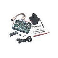
Kit Contents
Main Board, 2 Transmitters, Cables And Power Supply
Tool / Board Applications
General Purpose MCU, MPU, DSP, DSC
For Use With
KeeLoq
Lead Free Status / RoHS Status
Request inventory verification / Request inventory verification
For Use With/related Products
Keeloq Encoders & Decoders
Lead Free Status / RoHS Status
Lead free / RoHS Compliant, Request inventory verification / Request inventory verification


A socket (U5) for an additional external I
EEPROM (24LCXX) is provided for future expansion
as well as a standard 14-pin LCD display connector
(J6).
An In-Circuit Debugger compatible connector J4
(RJ11 type) can be mounted below the two buttons to
allow connection with the standard Microchip Flash
ICD Development Tool.
FIGURE 7-8:
7.5.2
The power supply circuit is designed to regulate a max-
imum current of 100 mA at 5V from two possible
sources:
• An external 9V battery, useful for demonstrations
• A power supply unit capable of providing an
An internal diode bridge allows the use of AC or DC
external power supply units; connector polarity is irrel-
evant.
A diode in the 9V battery circuit protects the board from
accidental reverse battery connections.
The Red and Black terminals in the Prototyping area
provide convenient +5V and GND connections, respec-
tively, to the custom circuitry.
The user must guarantee that the Prototype area cus-
tom circuit current draw added to the Main Board con-
sumption (varying with the number of decoders
mounted and their use) does not exceed the 100 mA
total limit.
2001 Microchip Technology Inc.
and ease of transport,
unregulated 9V – 15V.
POWER SUPPLY AND
PROTOTYPING AREA
THE SERIAL INTERFACE
RS-232 connector
RS-232 driver
K
EE
2
L
C™
OQ
®
EVALUATION KIT II USER’S GUIDE
7.5.1
A DB9 RS-232 serial interface connector is located on
the left side of the board. Four I/O lines connect the
Main Processor to the serial port. The RX and TX sig-
nals connect directly to the RC6 and RC7 UART pins
on the PICmicro MCU. The RTS and CTS hardware
handshake signals connect to the PICmicro microcon-
troller although the initial software release does not
make use of them.
A Microchip TC232C driver chip, or compatible, per-
forms full translation of the I/O levels to comply to RS-
232C specifications.
THE SERIAL INTERFACE
DS41155A-page 27
Related parts for DM303006
Image
Part Number
Description
Manufacturer
Datasheet
Request
R

Part Number:
Description:
Manufacturer:
Microchip Technology Inc.
Datasheet:
Part Number:
Description:
Manufacturer:
Microchip Technology Inc.
Datasheet:
Part Number:
Description:
Manufacturer:
Microchip Technology Inc.
Datasheet:
Part Number:
Description:
Manufacturer:
Microchip Technology Inc.
Datasheet:
Part Number:
Description:
Manufacturer:
Microchip Technology Inc.
Datasheet:
Part Number:
Description:
Manufacturer:
Microchip Technology Inc.
Datasheet:
Part Number:
Description:
Manufacturer:
Microchip Technology Inc.
Datasheet:
Part Number:
Description:
Manufacturer:
Microchip Technology Inc.
Datasheet: