DM303006 Microchip Technology, DM303006 Datasheet - Page 28
DM303006
Manufacturer Part Number
DM303006
Description
KIT EVALUATION KEELOQ
Manufacturer
Microchip Technology
Series
KEELOQ®r
Type
KeeLoq®r
Specifications of DM303006
Silicon Manufacturer
Microchip
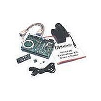
Kit Contents
Main Board, 2 Transmitters, Cables And Power Supply
Tool / Board Applications
General Purpose MCU, MPU, DSP, DSC
For Use With
KeeLoq
Lead Free Status / RoHS Status
Request inventory verification / Request inventory verification
For Use With/related Products
Keeloq Encoders & Decoders
Lead Free Status / RoHS Status
Lead free / RoHS Compliant, Request inventory verification / Request inventory verification


K
7.4.3
1.
2.
3.
4.
5.
6.
7.4.4
Erasing all the learned transmitters from memory is
accomplished by pressing and holding the LEARN but-
ton for 8 seconds. The LED will turn off at the end of the
8 seconds to indicate that the non-volatile memory has
been erased.
7.4.5
Press and hold the LEARN button. It will turn on for
about a second and then off again. Continue holding for
about 10 seconds until the LED turns on again. Only
then release the LEARN button. The LED will finally
turn off to indicate that the non-volatile memory has
been erased.
FIGURE 7-7:
DS41155A-page 26
EE
Press and hold the LEARN button until the
LEARN OUT LED first turns on and then off
about a second later.
Press any transmitter button.
The LEARN OUT LED will flash briefly.
Press any transmitter button if configured
for NORMAL Learn or the SEED button
combination if configured for SECURE Learn.
The LEARN OUT LED will flash for a second
time.
Press the transmitter again to determine if the
Learning attempt was successful. The LEARN
OUT LED will flash only if the transmitter was
successfully learned.
L
OQ
LEARNING ON AN HCS515
DECODER STEP BY STEP
TRANSMITTER ERASING ON
HCS512 AND SOFTWARE
DECODERS
TRANSMITTER ERASING ON
HCS515 DECODER
®
EVALUATION KIT II USER’S GUIDE
THE MAIN PROCESSOR AREA
I/O pads/vias
connectors
ICSP/ICD
BOOT
PIC16F877
LCD display connector
Socket for 24LCXX
7.5
The main processor area contains a TQFP PIC16F877
operating with a 20 MHz crystal clock (HS mode).
The microprocessor’s internal brown out circuit is dis-
abled as an external Microchip voltage supervisor
device MCP120 – 450 is used. The voltage supervisor
provides reset to both the PICmicro MCU and the
decoders when the supply drops below 4.5V; except
the HCS512 decoder, see below. 4.5V is the minimum
operating voltage of the PICmicro MCU when operating
at 20MHz.
The PCB area surrounding the PICmicro microcontrol-
ler provides easy access to the PICmicro MCU’s I/O’s
through about 40 pads/vias. The access points are
available for testing or connecting to the prototype
area.
Two button switches are available: RESET and BOOT.
The BOOT button is connected to the RB4 I/O pin as
well as to the HCS512 decoder’s separate reset line.
The BOOT button is used by the BOOT loader to down-
load new firmware into the Main Processor from the
Serial Port and bootstrap it into execution.
Reset
20 MHz
Crystal
The Main Processor
2001 Microchip Technology Inc.
Related parts for DM303006
Image
Part Number
Description
Manufacturer
Datasheet
Request
R

Part Number:
Description:
Manufacturer:
Microchip Technology Inc.
Datasheet:
Part Number:
Description:
Manufacturer:
Microchip Technology Inc.
Datasheet:
Part Number:
Description:
Manufacturer:
Microchip Technology Inc.
Datasheet:
Part Number:
Description:
Manufacturer:
Microchip Technology Inc.
Datasheet:
Part Number:
Description:
Manufacturer:
Microchip Technology Inc.
Datasheet:
Part Number:
Description:
Manufacturer:
Microchip Technology Inc.
Datasheet:
Part Number:
Description:
Manufacturer:
Microchip Technology Inc.
Datasheet:
Part Number:
Description:
Manufacturer:
Microchip Technology Inc.
Datasheet: