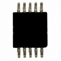
SI4010-B1-GT Silicon Laboratories Inc, SI4010-B1-GT Datasheet - Page 36

SI4010-B1-GT
Manufacturer Part Number
SI4010-B1-GT
Description
IC TX 27-960MHZ FSK 3.6V 10MSOP
Manufacturer
Silicon Laboratories Inc
Series
EZRadio®r
Type
ISM Transmitterr
Datasheets
1.4010-DAAKF_434.pdf
(2 pages)
2.SI4010-B1-GS.pdf
(160 pages)
3.SI4010-C2-GS.pdf
(156 pages)
Specifications of SI4010-B1-GT
Package / Case
10-MSOP, Micro10™, 10-uMAX, 10-uSOP
Frequency
27MHz ~ 960MHz
Applications
Garage Openers, RKE, Security Alarms
Modulation Or Protocol
FSK, OOK
Data Rate - Maximum
100 kBaud
Power - Output
10dBm
Current - Transmitting
19.8mA
Data Interface
PCB, Surface Mount
Antenna Connector
PCB, Surface Mount
Memory Size
4kB RAM
Features
8051 MCU Core, Crystal-less Operation
Voltage - Supply
1.8 V ~ 3.6 V
Operating Temperature
-40°C ~ 85°C
Operating Frequency
27 MHz to 960 MHz
Maximum Operating Temperature
+ 85 C
Mounting Style
SMD/SMT
Operating Supply Voltage
1.8 V to 3.6 V
Supply Current
10 mA
Lead Free Status / RoHS Status
Lead free / RoHS Compliant
Other names
336-1973-5
Si4010
These parameters are discussed in more detail in the Power Amplifier section of the data sheet. Based on
these input parameters the calculator will provide the following outputs:
PA Design Values:
Antenna Targets:
Chip Impedance:
API: PA Setup:
36
Manual Impedance Entry: Determines if the antenna impedance is calculated to meet a desired output
power or if the antenna impedance is entered and the spread sheet calculates the resulting impedance.
The current drive is adjusted to meet the power target (if possible).
Antenna Real(Z) (Ohms): The antenna resistance at the operating frequency.
Antenna Imag(Z) (Ohms): The antenna reactance at the operating frequency.
Iout Target (mA): Theoretical output current that meets the power target.
Attenuation Factor: Theoretical attenuation factor due to losses from the chip
Actual Iout (mA): The actual output current delivered to the antenna that accounts for quantization
effects and chip losses.
Rdif at PA (Ohms): Theoretical optimum differential load resistance that includes chip, antenna, and
external capacitance loading.
Total Power (dBm): The estimated output power based on all loss mechanisms.
Max Diff Vpk at PA (V): The calculated peak differential voltage swing.
Real_Z (Ohms): The required resistance of the antenna at the frequency of operation to meet the
desired output power.
Imag_Z (Ohms): The required reactance of the antenna at the frequency of operation to meet the
desired output power.
Power dissipated in Antenna (dBm): The expected power delivered to the antenna.
Expected Radiated Power (dBm): The expected radiated power of the device given the antenna
efficiency
Total Diff Cap due to Chip + External Load (pF): The equivalent differential capacitance seen looking
into the package pins. It includes the on-chip varactor, the package and external differential capacitor (if
used).
Real_Z (Ohms): The resistance of the chip at the frequency of operation to meet the desired output
power
Imag_Z (Ohms): The reactance of the chip at the frequency of operation to meet the desired output
power
bMaxDrv—value for this API parameter
bLevel—value for this API parameter
wCap—value for this API parameter
fAlpha—value for this API parameter
fBeta—value for this API parameter. The sensitivity of the antenna resistance vs capacitance change. If
constant radiated power vs tuning capacitance change is desired this constant may be used to
compensate the PA drive strength. See the API section on power control. The algorithm attempts to
keep the PA output voltage multiplied by the PA capacitance constant due to fluctuations in the external
component values of the loop antenna.
Rev. 0.5


