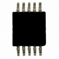
SI4010-B1-GT Silicon Laboratories Inc, SI4010-B1-GT Datasheet - Page 77

SI4010-B1-GT
Manufacturer Part Number
SI4010-B1-GT
Description
IC TX 27-960MHZ FSK 3.6V 10MSOP
Manufacturer
Silicon Laboratories Inc
Series
EZRadio®r
Type
ISM Transmitterr
Datasheets
1.4010-DAAKF_434.pdf
(2 pages)
2.SI4010-B1-GS.pdf
(160 pages)
3.SI4010-C2-GS.pdf
(156 pages)
Specifications of SI4010-B1-GT
Package / Case
10-MSOP, Micro10™, 10-uMAX, 10-uSOP
Frequency
27MHz ~ 960MHz
Applications
Garage Openers, RKE, Security Alarms
Modulation Or Protocol
FSK, OOK
Data Rate - Maximum
100 kBaud
Power - Output
10dBm
Current - Transmitting
19.8mA
Data Interface
PCB, Surface Mount
Antenna Connector
PCB, Surface Mount
Memory Size
4kB RAM
Features
8051 MCU Core, Crystal-less Operation
Voltage - Supply
1.8 V ~ 3.6 V
Operating Temperature
-40°C ~ 85°C
Operating Frequency
27 MHz to 960 MHz
Maximum Operating Temperature
+ 85 C
Mounting Style
SMD/SMT
Operating Supply Voltage
1.8 V to 3.6 V
Supply Current
10 mA
Lead Free Status / RoHS Status
Lead free / RoHS Compliant
Other names
336-1973-5
- Current page: 77 of 160
- Download datasheet (831Kb)
The IDE debugging environment can be used only with the Factory and User program chip levels, not with
the Run part.
23.4. NVM Organization
The 8KB NVM (OTP) memory is virtually mapped to the device address space 0xE000 .. 0xFFFF. How-
ever, CPU can access NVM only indirectly using the predefined API calls in ROM.
The NVM address region is organized in the following fashion:
1. Factory region .. factory settings critical for chip functions. Size is variable based on the device
2. User region .. region available for User application load at boot time. If the user application is not going
3. User App optional region .. optional region not visible at boot time. If the user application is using
4. Reserved region .. last 64 bytes of NVM are reserved for factory use and not available for user load.
The User load can occupy the rest of the NVM. The user may decide that he will use overlays. That means
that the boot routine will not copy all the data from NVM to RAM upon boot, but during the runtime of the
user program the program itself will load data from NVM to the RAM as desired. Only the User region is
known to boot routine and will be loaded during boot.
The User App region is the data region available to the user for a load to be loaded at runtime by the user
program. The user will have to call the API NVM copy routine in that case. The application note will
describe this process in detail. In such a scenario, this NVM region will not be loaded by boot, but by the
user application. That region of NVM is labeled as User App region in Figure 23.1, “NVM Address Map”.
Boot routine will not know about the data there.
NVM to RAM, the boot loader executes a jump to RAM address 0x0000 and the user application is
executed. The C2 is not enabled in this mode with the retest exception, briefly described in this
document.
configuration.
to use overlays, then this will be the only user data region used.
overlays, then the overlay code will be stored in this region. It will be up to the user to load the
application code from the NVM to CODE/XDATA RAM at runtime based on the user application
request. Application note will be devoted to this technique.
Rev. 0.5
Si4010
77
Related parts for SI4010-B1-GT
Image
Part Number
Description
Manufacturer
Datasheet
Request
R
Part Number:
Description:
SI4010-C2-GSR
Manufacturer:
Silicon Laboratories Inc
Datasheet:
Part Number:
Description:
MSOP 10/I°/SOC RF TRANSMITTER WITH 8051
Manufacturer:
Silicon Laboratories Inc

Part Number:
Description:
IC TX 27-960MHZ FSK 3.6V 10MSOP
Manufacturer:
Silicon Laboratories Inc
Datasheet:
Part Number:
Description:
IC TX 27-960MHZ FSK 3.6V 14SOIC
Manufacturer:
Silicon Laboratories Inc
Datasheet:
Part Number:
Description:
IC TX 27-960MHZ FSK 3.6V 14SOIC
Manufacturer:
Silicon Laboratories Inc
Datasheet:
Part Number:
Description:
SMD/C°/SINGLE-ENDED OUTPUT SILICON OSCILLATOR
Manufacturer:
Silicon Laboratories Inc
Part Number:
Description:
Manufacturer:
Silicon Laboratories Inc
Datasheet:
Part Number:
Description:
N/A N/A/SI4010 AES KEYFOB DEMO WITH LCD RX
Manufacturer:
Silicon Laboratories Inc
Datasheet:
Part Number:
Description:
N/A N/A/SI4010 SIMPLIFIED KEY FOB DEMO WITH LED RX
Manufacturer:
Silicon Laboratories Inc
Datasheet:
Part Number:
Description:
N/A/-40 TO 85 OC/EZLINK MODULE; F930/4432 HIGH BAND (REV E/B1)
Manufacturer:
Silicon Laboratories Inc
Part Number:
Description:
EZLink Module; F930/4432 Low Band (rev e/B1)
Manufacturer:
Silicon Laboratories Inc
Part Number:
Description:
I°/4460 10 DBM RADIO TEST CARD 434 MHZ
Manufacturer:
Silicon Laboratories Inc
Part Number:
Description:
I°/4461 14 DBM RADIO TEST CARD 868 MHZ
Manufacturer:
Silicon Laboratories Inc
Part Number:
Description:
I°/4463 20 DBM RFSWITCH RADIO TEST CARD 460 MHZ
Manufacturer:
Silicon Laboratories Inc


