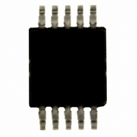
SI4010-B1-GT Silicon Laboratories Inc, SI4010-B1-GT Datasheet - Page 6

SI4010-B1-GT
Manufacturer Part Number
SI4010-B1-GT
Description
IC TX 27-960MHZ FSK 3.6V 10MSOP
Manufacturer
Silicon Laboratories Inc
Series
EZRadio®r
Type
ISM Transmitterr
Datasheets
1.4010-DAAKF_434.pdf
(2 pages)
2.SI4010-B1-GS.pdf
(160 pages)
3.SI4010-C2-GS.pdf
(156 pages)
Specifications of SI4010-B1-GT
Package / Case
10-MSOP, Micro10™, 10-uMAX, 10-uSOP
Frequency
27MHz ~ 960MHz
Applications
Garage Openers, RKE, Security Alarms
Modulation Or Protocol
FSK, OOK
Data Rate - Maximum
100 kBaud
Power - Output
10dBm
Current - Transmitting
19.8mA
Data Interface
PCB, Surface Mount
Antenna Connector
PCB, Surface Mount
Memory Size
4kB RAM
Features
8051 MCU Core, Crystal-less Operation
Voltage - Supply
1.8 V ~ 3.6 V
Operating Temperature
-40°C ~ 85°C
Operating Frequency
27 MHz to 960 MHz
Maximum Operating Temperature
+ 85 C
Mounting Style
SMD/SMT
Operating Supply Voltage
1.8 V to 3.6 V
Supply Current
10 mA
Lead Free Status / RoHS Status
Lead free / RoHS Compliant
Other names
336-1973-5
Si4010
L
6
I S T OF
Figure 1.1. Si4010 Block Diagram ........................................................................... 12
Figure 2.1. Test Block Diagram with 10-pin MSOP ................................................. 13
Figure 3.1. Si4010 Used in a 5-button RKE System with LED Indicator .................. 14
Figure 3.2. Si4010 with an External Crystal in a 4-button RKE System
Figure 6.1. 10-pin MSOP Package .......................................................................... 20
Figure 6.2. 14-pin SOIC Package ............................................................................ 21
Figure 7.1. 10-Pin MSOP Recommended PCB Land Pattern ................................. 22
Figure 8.1. 14-pin SOIC Recommended PCB Land Pattern .................................... 24
Figure 10.1. Functional Block Diagram .................................................................... 33
Figure 11.1. Simplified PA Block Diagram ............................................................... 42
Figure 12.1. OOK Timing Example .......................................................................... 46
Figure 12.2. FSK Timing Example ........................................................................... 46
Figure 16.1. Frequency Counter Block Diagram ...................................................... 56
Figure 21.1. CIP-51 Block Diagram ......................................................................... 61
Figure 22.1. Address Space Map after the Boot ...................................................... 71
Figure 23.1. NVM Address Map ............................................................................... 78
Figure 23.2. CODE/XDATA RAM Address Map ...................................................... 80
Figure 23.3. Boot Routine Destination CPU Address Space for Copy from NVM ... 84
Figure 29.1. Device Package and Port Assignments ............................................. 112
Figure 29.2. GPIO[3:1] Functional Diagram ........................................................... 114
Figure 29.3. Other GPIO Functional Diagram ........................................................ 114
Figure 29.4. Push Button Organization in Matrix Mode ......................................... 117
Figure 29.5. GPIO[5] LED Driver Block Diagram ................................................... 121
Figure 30.1. Output Clock Generator Block Diagram ............................................ 127
Figure 32.1. RTC Timer Block Diagram ................................................................. 132
Figure 33.1. Timer Interrupt Generation ................................................................ 136
Figure 33.2. Timer 16-bit Mode Block Diagram (Wide Mode) ................................ 137
Figure 33.3. Capture 16-bit Mode Block Diagram (Wide Mode) ............................ 138
Figure 33.4. Two 8-bit Timers in Timer/Timer Configuration (Split Mode) ............. 139
Figure 33.5. Two 8-bit Timers in Capture/Capture Configuration (Split Mode) ...... 140
Figure 33.6. Two 8-bit TImers in Timer/Capture Configuration (Split Mode) ......... 141
Figure 33.7. Two 8-bit Timers In Capture/Timer Configuration (Split Mode) ......... 142
Figure 34.1. 10-pin C2 USB Debugging Adapter Connection to Device ................ 152
Figure 34.2. 14-pin C2 ToolStick Connection to Device ........................................ 154
F
with LED Indicator 14
IGURES
Rev. 0.5


