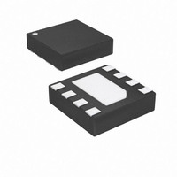
ATTINY5-MAH Atmel, ATTINY5-MAH Datasheet - Page 93

ATTINY5-MAH
Manufacturer Part Number
ATTINY5-MAH
Description
IC MCU AVR 512B FLASH 8UDFN
Manufacturer
Atmel
Series
AVR® ATtinyr
Specifications of ATTINY5-MAH
Core Processor
AVR
Core Size
8-Bit
Speed
12MHz
Peripherals
POR, PWM, WDT
Number Of I /o
4
Program Memory Size
512B (256 x 16)
Program Memory Type
FLASH
Ram Size
32 x 8
Voltage - Supply (vcc/vdd)
1.8 V ~ 5.5 V
Data Converters
A/D 4x8b
Oscillator Type
Internal
Operating Temperature
-40°C ~ 85°C
Package / Case
8-UFDFN Exposed Pad
Core
AVR8
Lead Free Status / RoHS Status
Lead free / RoHS Compliant
Eeprom Size
-
Connectivity
-
Lead Free Status / Rohs Status
Details
- Current page: 93 of 169
- Download datasheet (5Mb)
13.11 ADC Conversion Result
8127D–AVR–02/10
Figure 13-12. Differential Non-linearity (DNL)
After the conversion is complete (ADIF is high), the conversion result can be found in the ADC
Data Register (ADCL). For single ended conversion, the result is
where V
voltage reference. 0x00 represents analog ground, and 0xFF represents the selected reference
voltage minus one LSB.
• Differential Non-linearity (DNL): The maximum deviation of the actual code width (the interval
• Quantization Error: Due to the quantization of the input voltage into a finite number of codes,
• Absolute Accuracy: The maximum deviation of an actual (unadjusted) transition compared to
between two adjacent transitions) from the ideal code width (1 LSB). Ideal value: 0 LSB.
a range of input voltages (1 LSB wide) will code to the same value. Always ± 0.5 LSB.
an ideal transition for any code. This is the compound effect of offset, gain error, differential
error, non-linearity, and quantization error. Ideal value: ± 0.5 LSB.
Output Code
IN
(see
0x00
0xFF
Table 13-2 on page
0
1 LSB
94) is the voltage on the selected input pin and V
ADCL
=
V
---------------------- -
IN
V
⋅
CC
256
V
ATtiny4/5/9/10
REF
Input Voltage
CC
is the
93
Related parts for ATTINY5-MAH
Image
Part Number
Description
Manufacturer
Datasheet
Request
R

Part Number:
Description:
Manufacturer:
Atmel Corporation
Datasheet:

Part Number:
Description:
IC MCU AVR 512B FLASH SOT-23-6
Manufacturer:
Atmel
Datasheet:

Part Number:
Description:
IC MCU AVR 512B FLASH 8UDFN
Manufacturer:
Atmel
Datasheet:

Part Number:
Description:
IC MCU AVR 512B FLASH SOT-23-6
Manufacturer:
Atmel
Datasheet:

Part Number:
Description:
IC, MCU, 8BIT, 2K FLASH, 20SOIC
Manufacturer:
Atmel
Datasheet:

Part Number:
Description:
IC, MCU, 8BIT, 2K FLASH, 20PDIP
Manufacturer:
Atmel
Datasheet:

Part Number:
Description:
IC, MCU, 8BIT, 8K FLASH, 20PDIP
Manufacturer:
Atmel
Datasheet:

Part Number:
Description:
IC, MCU, 8BIT, 8K FLASH, 20SOIC
Manufacturer:
Atmel
Datasheet:

Part Number:
Description:
DEV KIT FOR AVR/AVR32
Manufacturer:
Atmel
Datasheet:

Part Number:
Description:
INTERVAL AND WIPE/WASH WIPER CONTROL IC WITH DELAY
Manufacturer:
ATMEL Corporation
Datasheet:

Part Number:
Description:
Low-Voltage Voice-Switched IC for Hands-Free Operation
Manufacturer:
ATMEL Corporation
Datasheet:

Part Number:
Description:
MONOLITHIC INTEGRATED FEATUREPHONE CIRCUIT
Manufacturer:
ATMEL Corporation
Datasheet:

Part Number:
Description:
AM-FM Receiver IC U4255BM-M
Manufacturer:
ATMEL Corporation
Datasheet:

Part Number:
Description:
Monolithic Integrated Feature Phone Circuit
Manufacturer:
ATMEL Corporation
Datasheet:


