AD6620AS Analog Devices Inc, AD6620AS Datasheet - Page 22
AD6620AS
Manufacturer Part Number
AD6620AS
Description
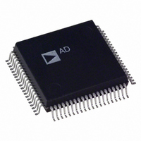
IC DGTL RCVR SIGNAL PROC 80-PQFP
Manufacturer
Analog Devices Inc
Datasheet
1.AD6620SPCB.pdf
(44 pages)
Specifications of AD6620AS
Rohs Status
RoHS non-compliant
Interface
Parallel/Serial
Voltage - Supply
3 V ~ 3.6 V
Package / Case
80-MQFP, 80-PQFP
Mounting Type
*
Applications
-
Available stocks
Company
Part Number
Manufacturer
Quantity
Price

Part Number:
AD6620AS
Manufacturer:
ADI/亚德诺
Quantity:
20 000
Company:
Part Number:
AD6620ASZ
Manufacturer:
Analog Devices Inc
Quantity:
10 000
Company:
Part Number:
AD6620ASZ-REEL
Manufacturer:
Analog Devices Inc
Quantity:
10 000


The equations for calculating CIC2 output level is correct when
stage is not bypassed (normal operation). However, when by-
passed, the following equations should be used instead.
The gain and pass band droop of the CIC2 should be calculated
by the equations above, as well as the filter transfer equations
that follow. If these are unacceptable, they can be compensated
for in subsequent stages.
CIC2 Rejection
The table below illustrates the amount of bandwidth in percent
of the data rate into the CIC2 stage. The data in this table may
be scaled to any allowable sample rate up to 67 MHz in Single
Channel Mode or 33.5 MHz in Diversity Channel Mode. The
table can be used as a tool to decide how to distribute the deci-
mation between CIC2, CIC5 and the RCF.
The data in this table may be scaled to any allowable sample
rate up to 67 MHz in Single Channel Mode or 33.5 MHz in
Diversity Channel Mode.
M
2
3
4
5
6
7
8
9
10
11
12
13
14
15
16
Example Calculations
Goal: Implement a filter with an Input Sample Rate of 10 MHz
requiring 100 dB of Alias Rejection for a ± 7 kHz pass band.
Solution: First determine the percentage of the sample rate that
is represented by the pass band.
Find the –100 dB column on the right of the table and look
down this column for a value greater than or equal to your
pass band percentage of the clock rate. Then look across to the
extreme left column and find the corresponding decimation
rate. Referring to the table, notice that for a decimation of 4, the
frequency having –100 dB of alias rejection is 0.071 percent
AD6620
CIC2
Table III. SSB CIC2 Alias Rejection Table (f
Bandwidth Shown in Percentage of f
–50 dB –60 dB –70 dB –80 dB –90 dB –100 dB
1.79
1.508
1.217
1.006
0.853
0.739
0.651
0.581
0.525
0.478
0.439
0.406
0.378
0.353
0.331
S
BW
CIC
2
FRACTION
=
OL
1.007
0.858
0.696
0.577
0.49
0.425
0.374
0.334
0.302
0.275
0.253
0.234
0.217
0.203
0.19
ceil
CIC
OL
2
log (
CIC2
=
=
100
2
0.566
0.486
0.395
0.328
0.279
0.242
0.213
0.19
0.172
0.157
0.144
0.133
0.124
0.116
0.109
2
S
1
= Input Level
M
CIC
2
CIC
×
×
10
2
input level
7
2
kHz
MHz
0.318
0.274
0.223
0.186
0.158
0.137
0.121
0.108
0.097
0.089
0.082
0.075
0.07
0.066
0.061
×
input level
_
SAMP
=
_
0 07
0.179
0.155
0.126
0.105
0.089
0.077
0.068
0.061
0.055
0.05
0.046
0.043
0.04
0.037
0.035
.
SAMP
%
)
= 1)
0.101
0.087
0.071
0.059
0.05
0.044
0.038
0.034
0.031
0.028
0.026
0.024
0.022
0.021
0.02
which is slightly greater than the 0.07 percent calculated. There-
fore, the maximum bound on CIC2 decimation for this condi-
tion is four. Additional decimation means less alias rejection
than the 100 dB required.
Note that although an M
required rejection, overall power consumption is reduced by
decimating as much as possible in this stage. Decimation in
CIC2 lowers the data rate and thus reduces power consumed in
subsequent stages.
The plot below shows the CIC2 transfer function using a deci-
mation of four. The first plot is referenced to the input sample
rate, the complex spectrum from –f
ond plot is referenced to the CIC2 output rate, the complex
spectrum from –f
can be seen to be “folding back” in toward the edge of the
desired filter pass band. It is the level of these aliases as they
move into the desired pass band that are important.
The set of plots below show a decimation of 16 in the CIC2
filter. The lobes of the filter drop as the decimation rate
increases, but the amplitudes of the aliased frequencies increase
because the output rate has been reduced.
–100
–120
–100
–120
–20
–40
–60
–80
–20
–40
–60
–80
–0.5
–0.5
0
0
–0.4 –0.3 –0.2
–0.4 –0.3 –0.2
SAMP2
/2 to f
CIC2
–0.1
–0.1
SAMP2
less then four would still yield the
f/f
f/f
SAMP2
SAMP
0
0
/2. The aliases of the CIC2
SAMP
0.1
0.1
/2 to f
0.2
0.2
SAMP
0.3
0.3
/2. The sec-
0.4
0.4
0.5
0.5
Related parts for AD6620AS
Image
Part Number
Description
Manufacturer
Datasheet
Request
R

Part Number:
Description:
±1.7g Dual-Axis IMEMS Accelerometer Evaluation Board
Manufacturer:
Analog Devices Inc
Datasheet:

Part Number:
Description:
Inertial Sensor Evaluation System
Manufacturer:
Analog Devices Inc
Datasheet:
Part Number:
Description:
Manufacturer:
Analog Devices Inc
Datasheet:
Part Number:
Description:
Manufacturer:
Analog Devices Inc
Datasheet:
Part Number:
Description:
Manufacturer:
Analog Devices Inc
Datasheet:
Part Number:
Description:
Manufacturer:
Analog Devices Inc
Datasheet:
Part Number:
Description:
Manufacturer:
Analog Devices Inc
Datasheet:
Part Number:
Description:
Manufacturer:
Analog Devices Inc
Datasheet:
Part Number:
Description:
Manufacturer:
Analog Devices Inc
Datasheet:
Part Number:
Description:
Manufacturer:
Analog Devices Inc
Datasheet:
Part Number:
Description:
Manufacturer:
Analog Devices Inc
Datasheet:
Part Number:
Description:
Manufacturer:
Analog Devices Inc
Datasheet:
Part Number:
Description:
Manufacturer:
Analog Devices Inc
Datasheet: