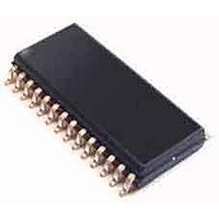
CS8427-CZZ Cirrus Logic Inc, CS8427-CZZ Datasheet - Page 17

CS8427-CZZ
Manufacturer Part Number
CS8427-CZZ
Description
Audio DSPs 96 kHz Digital Audio Transceiver
Manufacturer
Cirrus Logic Inc
Datasheet
1.CS8427-DZZ.pdf
(60 pages)
Specifications of CS8427-CZZ
Operating Supply Voltage
4.5 V to 5.5 V
Supply Current
6.3 mA to 76.6 mA
Operating Temperature Range
- 10 C to + 70 C
Mounting Style
SMD/SMT
Input Voltage
4.8 V to 5.8 V
Package / Case
TSSOP-28
Rohs Compliant
Yes
Supply Voltage Range
4.5V To 5.5V
Logic Case Style
TSSOP
No. Of Pins
28
Supply Voltage Max
5.5V
Supply Voltage Min
4.5V
Lead Free Status / RoHS Status
Lead free / RoHS Compliant
Available stocks
Company
Part Number
Manufacturer
Quantity
Price
Company:
Part Number:
CS8427-CZZ
Manufacturer:
CIRRUS
Quantity:
67
Part Number:
CS8427-CZZ
Manufacturer:
CIRRUS
Quantity:
20 000
General on the incoming AES3 stream, copyright
will always be indicated even when the stream in-
dicates no copyright. Finally, the AUDIO bit is ex-
tracted and used to set an AUDIO indicator, as
described in the Non-Audio Auto-Detection section
below.
If 50/15 µs pre-emphasis is detected, the state of
the EMPH pin is adjusted accordingly.
The encoded channel status bits which indicate
sample word length are decoded according to
AES3-1992 or IEC 60958. Audio data routed to the
serial audio output port is unaffected by the word
length settings - all 24 bits are passed on as re-
ceived.
“Appendix B: Channel Status and User Data Buffer
Management” on page 52
handling of Channel Status and User bit data.
6.5
The incoming user data is buffered in a user acces-
sible buffer. Various automatic modes of re-trans-
mitting received User data are provided. The
Appendix: Channel Status and User Data Buffer
Management describes the overall handling of CS
and U data.
Received User data may also be output to the U
pin, under the control of a control register bit. De-
pending on the data flow and clocking options se-
lected, there may not be a clock available to qualify
the U data output.
DS477F5
User Data Handling
Figure 13
describes the overall
illustrates the timing.
If the incoming user data bits have been encoded
as Q-channel subcode, the data is decoded and
presented in ten consecutive register locations. An
interrupt may be enabled to indicate the decoding
of a new Q-channel block, which may be read
through the control port.
6.6
An AES3 data stream may be used to convey non-
audio data, thus it is important to know whether the
incoming AES3 data stream is digital audio or not.
This information is typically conveyed in channel
status bit 1 (AUDIO), which is extracted automati-
cally by the CS8427. However, certain non-audio
sources, such as AC3
not adhere to this convention, and the bit may not
be properly set. The CS8427 AES3 receiver can
detect such non-audio data. This is accomplished
by looking for a 96-bit sync code, consisting of
0x0000, 0x0000, 0x0000, 0x0000, 0xF872, and
0x4E1F. When the sync code is detected, an inter-
nal AUTODETECT signal will be asserted. If no ad-
ditional sync codes are detected within the next
4096 frames, AUTODETECT will be de-asserted
until another sync code is detected. The AUDIO bit
in the Receiver Channel Status register is the logi-
cal OR of AUTODETECT and the received chan-
nel status bit 1. If non-audio data is detected, the
data is still processed exactly as if it were normal
audio. It is up to the user to mute the outputs as re-
quired.
Non-Audio Auto Detection
or MPEG encoders, may
CS8427
17


