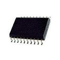
PCA9634PW NXP Semiconductors, PCA9634PW Datasheet - Page 10

PCA9634PW
Manufacturer Part Number
PCA9634PW
Description
IC, LED DRIVER, RGBA, 20-TSSOP
Manufacturer
NXP Semiconductors
Datasheet
1.PCA9634D112.pdf
(38 pages)
Specifications of PCA9634PW
No. Of Outputs
8
Output Current
25mA
Output Voltage
5.5V
Input Voltage
2.3V To 5.5V
Dimming Control Type
PWM
Driver Case Style
TSSOP
Switching Frequency
1MHz
Base Number
9634
Operating
RoHS Compliant
Number Of Segments
16
Low Level Output Current
200 mA
High Level Output Current
50 uA
Operating Supply Voltage
2.3 V to 5.5 V
Maximum Supply Current
10 mA
Maximum Power Dissipation
400 mW
Maximum Operating Temperature
+ 85 C
Mounting Style
SMD/SMT
Package / Case
TSSOP-20
Minimum Operating Temperature
- 40 C
Led Driver Application
RGB Or RGBA LED Drivers, LED Status Information, Displays, Backlights
Rohs Compliant
Yes
Lead Free Status / Rohs Status
Details
Available stocks
Company
Part Number
Manufacturer
Quantity
Price
Company:
Part Number:
PCA9634PW
Manufacturer:
TRINAMIC
Quantity:
1 200
Company:
Part Number:
PCA9634PW
Manufacturer:
NXP Semiconductors
Quantity:
26 963
Part Number:
PCA9634PW
Manufacturer:
NXP/恩智浦
Quantity:
20 000
NXP Semiconductors
Table 4.
Only D[4:0] = 0 0000 to 1 0001 are allowed and will be acknowledged.
D[4:0] = 1 0010 to 1 1111 are reserved and will not be acknowledged.
PCA9634_6
Product data sheet
Register number (hex)
00
01
02
03
04
05
06
07
08
09
0A
0B
0C
0D
0E
0F
10
11
Register summary
7.3 Register definitions
AI[2:0] = 110 is used when the LED drivers must be globally programmed with different
settings during the same I
blinking change.
AI[2:0] = 111 is used when individual and global changes must be performed during the
same I
same time.
Only the 5 least significant bits D[4:0] are affected by the AI[2:0] bits.
When the Control register is written, the register entry point determined by D[4:0] is the
first register that will be addressed (read or write operation), and can be anywhere
between 0 0000 and 1 0001 (as defined in
flag is set and the rollover value at which the register increment stops and goes to the next
one is determined by AI[2:0]. See
register = 1110 1100 (ECh), then the register addressing sequence will be (in hex):
0C
as the master keeps sending or reading data.
D4
0
0
0
0
0
0
0
0
0
0
0
0
0
0
0
0
1
1
…
2
C-bus communication, for example, changing a color and global brightness at the
D3
0
0
0
0
0
0
0
0
1
1
1
1
1
1
1
1
0
0
11
D2
0
0
0
0
1
1
1
1
0
0
0
0
1
1
1
1
0
0
00
Rev. 06 — 12 September 2008
D1
0
0
1
1
0
0
1
1
0
0
1
1
0
0
1
1
0
0
…
2
D0
0
1
0
1
0
1
0
1
0
1
0
1
0
1
0
1
0
1
C-bus communication, for example, global brightness or
0B
Name
MODE1
MODE2
PWM0
PWM1
PWM2
PWM3
PWM4
PWM5
PWM6
PWM7
GRPPWM
GRPFREQ
LEDOUT0
LEDOUT1
SUBADR1
SUBADR2
SUBADR3
ALLCALLADR
Table 3
02
for rollover values. For example, if the Control
…
Table
0B
Type
read/write
read/write
read/write
read/write
read/write
read/write
read/write
read/write
read/write
read/write
read/write
read/write
read/write
read/write
read/write
read/write
read/write
read/write
4). When AI[2] = 1, the Auto-Increment
02
8-bit Fm+ I
…
Function
Mode register 1
Mode register 2
brightness control LED0
brightness control LED1
brightness control LED2
brightness control LED3
brightness control LED4
brightness control LED5
brightness control LED6
brightness control LED7
group duty cycle control
group frequency
LED output state 0
LED output state 1
I
I
I
LED All Call I
2
2
2
C-bus subaddress 1
C-bus subaddress 2
C-bus subaddress 3
0B
PCA9634
2
© NXP B.V. 2008. All rights reserved.
C-bus LED driver
02
2
C-bus address
… as long
10 of 38


