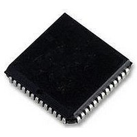
SC16C754BIA68 NXP Semiconductors, SC16C754BIA68 Datasheet - Page 15

SC16C754BIA68
Manufacturer Part Number
SC16C754BIA68
Description
IC, UART, QUAD, 64BYTE FIFO, 16C754
Manufacturer
NXP Semiconductors
Datasheet
1.SC16C754BIA68.pdf
(51 pages)
Specifications of SC16C754BIA68
No. Of Channels
4
Data Rate
5Mbps
Supply Voltage Range
2.25V To 5.5V
Operating Temperature Range
-40°C To +85°C
Digital Ic Case Style
PLCC
No. Of Pins
68
Svhc
No SVHC (18-Jun-2010)
Uart Features
DMA Signalling Capability, Software Selectable Baud Rate Generator
Rohs Compliant
Yes
Lead Free Status / RoHS Status
Lead free / RoHS Compliant
Available stocks
Company
Part Number
Manufacturer
Quantity
Price
Part Number:
SC16C754BIA68
Manufacturer:
NXP/恩智浦
Quantity:
20 000
Company:
Part Number:
SC16C754BIA68,512
Manufacturer:
NXP Semiconductors
Quantity:
10 000
Company:
Part Number:
SC16C754BIA68,518
Manufacturer:
NXP Semiconductors
Quantity:
10 000
Part Number:
SC16C754BIA68,518
Manufacturer:
NXP/恩智浦
Quantity:
20 000
Company:
Part Number:
SC16C754BIA68,529
Manufacturer:
NXP Semiconductors
Quantity:
10 000
NXP Semiconductors
Table 6.
SC16C754B_4
Product data sheet
IIR[5:0]
00 0001
00 0110
00 1100
00 0100
00 0010
00 0000
01 0000
10 0000
Interrupt control functions
Priority
level
None
1
2
2
3
4
5
6
6.5 Interrupts
The SC16C754B has interrupt generation and prioritization (six prioritized levels of
interrupts) capability. The Interrupt Enable Register (IER) enables each of the six types of
interrupts and the INT signal in response to an interrupt generation. The IER can also
disable the interrupt system by clearing bits 7:5 and 3:0. When an interrupt is generated,
the IIR indicates that an interrupt is pending and provides the type of interrupt through
IIR[5:0].
It is important to note that for the framing error, parity error, and break conditions, LSR[7]
generates the interrupt. LSR[7] is set when there is an error anywhere in the RX FIFO,
and is cleared only when there are no more errors remaining in the FIFO. LSR[4:2] always
represent the error status for the received character at the top of the RX FIFO. Reading
the RX FIFO updates LSR[4:2] to the appropriate status for the new character at the top of
the FIFO. If the RX FIFO is empty, then LSR[4:2] are all zeros.
For the Xoff interrupt, if an Xoff flow character detection caused the interrupt, the interrupt
is cleared by an Xon flow character detection. If a special character detection caused the
interrupt, the interrupt is cleared by a read of the IIR.
Interrupt type
none
receiver line status
RX time-out
RHR interrupt
THR interrupt
modem status
Xoff interrupt
CTS, RTS
Table 6
summarizes the interrupt control functions.
5 V, 3.3 V and 2.5 V quad UART, 5 Mbit/s (max.) with 64-byte FIFOs
Interrupt source
none
OE, FE, PE, or BI errors occur in
characters in the RX FIFO
stale data in RX FIFO
DRDY (data ready)
(FIFO disable)
RX FIFO above trigger level
(FIFO enable)
TFE (THR empty)
(FIFO disable)
TX FIFO passes above trigger level
(FIFO enable)
MSR[3:0] = 0
receive Xoff character(s)/special
character
RTS pin or CTS pin change state from
active (LOW) to inactive (HIGH)
Rev. 04 — 6 October 2008
Interrupt reset method
none
FE, PE, BI: all erroneous
characters are read from the
RX FIFO.
OE: read LSR
read RHR
read RHR
read IIR or a write to the THR
read MSR
receive Xon character(s)/Read of
IIR
read IIR
SC16C754B
© NXP B.V. 2008. All rights reserved.
15 of 51


