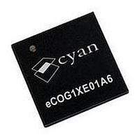
ECOG1XE01A6 CYAN, ECOG1XE01A6 Datasheet - Page 67

ECOG1XE01A6
Manufacturer Part Number
ECOG1XE01A6
Description
IC, 16BIT MCU, ECOG1X, 70MHZ, QFN-68
Manufacturer
CYAN
Datasheet
1.ECOG1X14Z5.pdf
(95 pages)
Specifications of ECOG1XE01A6
Controller Family/series
ECOG1X
No. Of I/o's
20
Ram Memory Size
8KB
Cpu Speed
70MHz
No. Of Timers
8
Digital Ic Case Style
QFN
Core Size
16 Bit
Program Memory Size
64KB
Embedded Interface Type
I2C, JTAG, SPI, UART
Rohs Compliant
Yes
Lead Free Status / RoHS Status
Lead free / RoHS Compliant
- Current page: 67 of 95
- Download datasheet (2Mb)
4 August 2009
Symbol
Symbol
T
t
t
t
t
t
t
N
N
t
t
CPU
DH
R1
R2
R3
DV
DS
A1
A2
DMA Mode
The tables below for the EHI function in DMA mode use the following symbols for time periods defined
by bit fields in the EHI registers.
DMA Mode - eCOG1X as master
1
2
Description
CPU clock period
EHI_ACK output active period (0..3)
EHI_ACK output inactive period (0..3)
Parameter
Delay time EHI_REQ active to EHI_ACK active
Delay time EHI_ACK active to
EHI_REQ inactive
Minimum EHI_REQ input inactive width
Minimum EHI_ACK output active width
Minimum EHI_ACK output inactive width
Delay time data output valid to EHI_ACK output active
Setup time data input valid to EHI_ACK output inactive
Hold time EHI_ACK output inactive to data input invalid
eCOG and CyanIDE are registered trademarks of Cyan Holdings plc
Figure 17: EHI DMA master write cycle timing diagram
Figure 16: EHI DMA master read cycle timing diagram
Table 34: AC characteristics - EHI DMA master mode
eCOG1X Microcontroller Product Family
Table 33: EHI clock symbols
www.cyantechnology.com
Continue next transfer (min)
Pause next transfer (max)
Definition
fd.ehi.cfg.dma_ack_act_prd1
fd.ehi.cfg.dma_ack_act_prd2
T
T
(2 x T
CPU
CPU
(T
CPU
Min
–3
13
CPU
x (N
x (N
0
0
0
x (N
) + 3
1
2
+ 1)
+ 1)
1
+ N
2
)) – 20
Max
+3
Version 1.15
Units
Units
ns
ns
ns
ns
ns
ns
ns
ns
ns
ns
67
Related parts for ECOG1XE01A6
Image
Part Number
Description
Manufacturer
Datasheet
Request
R

Part Number:
Description:
IC, 16BIT MCU, ECOG1X, 70MHZ, BGA-208
Manufacturer:
CYAN
Datasheet:

Part Number:
Description:
USB/Ethernet Gateway Board For Cy-Net3 Over RadioWire
Manufacturer:
CYAN
Datasheet:

Part Number:
Description:
USB/Ethernet Gateway Module For Cy-Net3 Over RadioWire
Manufacturer:
CYAN
Datasheet:

Part Number:
Description:
USB/Ethernet Gateway Board For Wireless M-BUS
Manufacturer:
CYAN
Datasheet:

Part Number:
Description:
USB/Ethernet Gateway Module For Wireless M-BUS
Manufacturer:
CYAN
Datasheet:

Part Number:
Description:
LED 5MM INGAN 505NM CYAN 23DEG
Manufacturer:
Avago Technologies US Inc.
Datasheet:

Part Number:
Description:
LED 5MM INGAN 505NM CYAN 23DEG
Manufacturer:
Avago Technologies US Inc.
Datasheet:

Part Number:
Description:
LED 5MM INGAN 505NM CYAN 30DEG
Manufacturer:
Avago Technologies US Inc.
Datasheet:

Part Number:
Description:
LED 1W STAR MCPCB CYAN INGAN
Manufacturer:
Lite-On Electronics
Datasheet:

Part Number:
Description:
LED SS 3MM CYAN WATER CLEAR
Manufacturer:
Kingbright Corp
Datasheet:

Part Number:
Description:
LED SS 5MM CYAN WATER CLEAR
Manufacturer:
Kingbright Corp
Datasheet:

Part Number:
Description:
LED 5MM INGAN 505NM CYAN 15DEG
Manufacturer:
Avago Technologies US Inc.
Datasheet:

Part Number:
Description:
LED 5MM INGAN 505NM CYAN 15DEG
Manufacturer:
Avago Technologies US Inc.
Datasheet:

Part Number:
Description:
LED 1W CYAN INGAN SMD
Manufacturer:
Lite-On Electronics
Datasheet:

Part Number:
Description:
LED, HIGH BRIGHTNESS, CYAN, 160LM
Manufacturer:
LUMILEDS
Datasheet:


