ST62T15CM6 STMicroelectronics, ST62T15CM6 Datasheet - Page 15
ST62T15CM6
Manufacturer Part Number
ST62T15CM6
Description
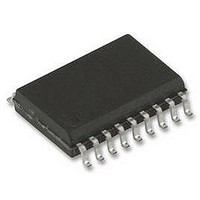
8BIT MCU OTP 2K, SMD, 62T15, SOIC20
Manufacturer
STMicroelectronics
Datasheet
1.ST62T15CB6.pdf
(105 pages)
Specifications of ST62T15CM6
Controller Family/series
ST6
Core Size
8bit
No. Of I/o's
20
Program Memory Size
2KB
Ram Memory Size
64Byte
Cpu Speed
8MHz
Oscillator Type
External Only
No. Of Timers
1
Digital Ic Case
RoHS Compliant
Peripherals
ADC,
Rohs Compliant
No
Processor Series
ST62T1x
Core
ST6
Data Bus Width
8 bit
Program Memory Type
EPROM
Data Ram Size
64 B
Maximum Clock Frequency
8 MHz
Number Of Programmable I/os
20
Number Of Timers
2
Operating Supply Voltage
3 V to 6 V
Maximum Operating Temperature
+ 85 C
Mounting Style
SMD/SMT
Package / Case
SOP-28
Development Tools By Supplier
ST62GP-EMU2, ST62E2XC-EPB/110, ST62E6XC-EPB/US, STREALIZER-II
Minimum Operating Temperature
- 40 C
On-chip Adc
8 bit
Lead Free Status / Rohs Status
In Transition
Available stocks
Company
Part Number
Manufacturer
Quantity
Price
Company:

Part Number:
ST62T15CM6
Manufacturer:
STM
Quantity:
2 508
Part Number:
ST62T15CM6
Manufacturer:
ST
Quantity:
20 000


3.2 PROGRAMMING MODES
3.2.1 Program Memory
EPROM/OTP programming mode is set by a
+12.5V voltage applied to the TEST/V
programming flow of the ST62T15C,T25C/E25C is
described in the User Manual of the EPROM Pro-
gramming Board.
Table 3. ST6215C Program Memory Map
Table 4. ST6225C Program Memory Map
Device Address
Device Address
0FFCh-0FFDh
0FFCh-0FFDh
0FA0h-0FEFh
0FF8h-0FFBh
0FFEh-0FFFh
0FA0h-0FEFh
0FF8h-0FFBh
0FFEh-0FFFh
0FF0h-0FF7h
0FF0h-0FF7h
0880h-0F9Fh
0080h-0F9Fh
0000h-087Fh
0000h-007Fh
NMI Interrupt Vector
NMI Interrupt Vector
Interrupt Vectors
Interrupt Vectors
Reset Vector
Reset Vector
Description
Description
User ROM
User ROM
Reserved
Reserved
Reserved
Reserved
Reserved
Reserved
PP
pin. The
Note: OTP/EPROM devices can be programmed
with
STMicroelectronics (please refer to
page
3.2.2 EPROM Erasing
The EPROM devices can be erased by exposure
to Ultra Violet light. The characteristics of the MCU
are such that erasure begins when the memory is
exposed to light with a wave lengths shorter than
approximately 4000Å. It should be noted that sun-
light and some types of fluorescent lamps have
wavelengths in the range 3000-4000Å.
It is thus recommended that the window of the
MCU packages be covered by an opaque label to
prevent unintentional erasure problems when test-
ing the application in such an environment.
The recommended erasure procedure is exposure
to short wave ultraviolet light which have a wave-
length 2537Å. The integrated dose (i.e. U.V. inten-
sity x exposure time) for erasure should be a mini-
mum of 30W-sec/cm
dosage is approximately 30 to 40 minutes using an
ultraviolet lamp with 12000µW/cm
The EPROM device should be placed within
2.5cm (1inch) of the lamp tubes during erasure.
100).
the
development tools
2
. The erasure time with this
ST6215C/ST6225C
available
2
Section 13 on
power rating.
15/105
from
1
Related parts for ST62T15CM6
Image
Part Number
Description
Manufacturer
Datasheet
Request
R

Part Number:
Description:
STMicroelectronics [RIPPLE-CARRY BINARY COUNTER/DIVIDERS]
Manufacturer:
STMicroelectronics
Datasheet:
Part Number:
Description:
STMicroelectronics [LIQUID-CRYSTAL DISPLAY DRIVERS]
Manufacturer:
STMicroelectronics
Datasheet:

Part Number:
Description:
BOARD EVAL FOR MEMS SENSORS
Manufacturer:
STMicroelectronics
Datasheet:
Part Number:
Description:
NPN TRANSISTOR POWER MODULE
Manufacturer:
STMicroelectronics
Datasheet:
Part Number:
Description:
TURBOSWITCH ULTRA-FAST HIGH VOLTAGE DIODE
Manufacturer:
STMicroelectronics
Datasheet:
Part Number:
Description:
Manufacturer:
STMicroelectronics
Datasheet:
Part Number:
Description:
DIODE / SCR MODULE
Manufacturer:
STMicroelectronics
Datasheet:
Part Number:
Description:
DIODE / SCR MODULE
Manufacturer:
STMicroelectronics
Datasheet:
Part Number:
Description:
Search -----> STE16N100
Manufacturer:
STMicroelectronics
Datasheet:
Part Number:
Description:
Search ---> STE53NA50
Manufacturer:
STMicroelectronics
Datasheet:
Part Number:
Description:
NPN Transistor Power Module
Manufacturer:
STMicroelectronics
Datasheet:
Part Number:
Description:
DIODE / SCR MODULE
Manufacturer:
STMicroelectronics
Datasheet: