PD3-013-42 TRINAMIC, PD3-013-42 Datasheet
PD3-013-42
Specifications of PD3-013-42


Related parts for PD3-013-42


PD3-013-42 Summary of contents
Page 1
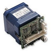
... PANdrive PD013-42 TMCM-013 and TMCM-013-LA STEPPER motor controller/driver module 1A RMS (1.5A peak) / 30V with RS485 and step-/ direction interface Trinamic Motion Control GmbH & Co. KG and Manual Sternstraß – 20357 Hamburg, Germany Phone +49-40- – 0 FAX: +49-40- – 60 http://www.trinamic.com ...
Page 2
... Option: Pseudo DC-Motor mode (not supported by software yet).......................................... 25 6.6.1 Changes required for DC motor mode operation............................................................... 25 6.6.2 Parameterizing with RS485 ............................................................................................... 26 6.6.3 Motion Control.................................................................................................................... 26 7 Revision History ............................................................................................................................. 27 7.1 Documentation Revision ......................................................................................................... 27 7.2 Firmware Revision .................................................................................................................. 27 Copyright © 2005, TRINAMIC Motion Control GmbH & Co. KG ...
Page 3
... Table 6.8: I/Os Readout ........................................................................................................................ 19 Table 6.9: Baud rate .............................................................................................................................. 19 Table 6.10: Adjustment of Microstep Resolution................................................................................... 20 Table 6.11: Chopper mode 3 switching velocities................................................................................. 22 Table 6.12: External signals and motor reactions ................................................................................. 22 Table 7.1: Documentation Revisions..................................................................................................... 27 Table 7.2: Firmware Revisions.............................................................................................................. 27 Copyright © 2005, TRINAMIC Motion Control GmbH & Co. KG ...
Page 4
... Many adjustment possibilities make this module the solution for a great field of demands Other • pluggable JST connectors • RoHS compliant latest from 1 July 2006 Order code PD1-013-42 PD2-013-42 PD3-013-42 TMCM-013 TMCM-013-LA Copyright © 2005, TRINAMIC Motion Control GmbH & Co. KG Description Dimensions [mm³] PANdrive 0.27Nm PANdrive 0.35Nm PANdrive 0 ...
Page 5
... Information given in this data sheet is believed to be accurate and reliable. However no responsibility is assumed for the consequences of its use nor for any infringement of patents or other rights of third parties, which may result form its use. Specifications subject to change without notice. Copyright © 2005, TRINAMIC Motion Control GmbH & Co. KG ...
Page 6
... RS485 - 16 RS485 remote control access -, TTL input OA1, OA2 Connections for motor coil A OB1, OB2 Connections for motor coil B Table 3.1: Pinning of TMCM-013 and TMCM-013-LA Copyright © 2005, TRINAMIC Motion Control GmbH & Co. KG Pin 16 RS485B Pin 15 RS485A Pin 14 GND REF B ...
Page 7
... TMCM-013-42 is 6.0mm and of the TMCM-013LA 12.5mm. Figure 3.2: Dimensions for TMCM-013 Figure 3.3: Dimensions for TMCM-013LA 3.3 Connectors Both connectors are crimp connectors series B4B-PH-SM3-TB, PH-connector. Motor: 4 pin connector Control: 16 pin connector Copyright © 2005, TRINAMIC Motion Control GmbH & Co. KG 36.5 mm 21.0 mm TMCM-013 36 36 ...
Page 8
... GPI V Output voltage on GPO and Alert GPO (open collector) I Output current on GPO and Alert GPO (open collector) T Environment temperature ENV operation Copyright © 2005, TRINAMIC Motion Control GmbH & Co. KG Min 440..1500 regulated, 300 .. 1000 << I 3.5 4 input -3 input (internally ...
Page 9
... Step Figure 4.1: Step, Direction and Disable Inputs Examples COM V OPTON STEP V = 20V COM V OPTON STEP Copyright © 2005, TRINAMIC Motion Control GmbH & Co. KG shall be tied to the positive supply voltage of the master and the COM OPTOFF GND undefined 1.5V undefined 16 ...
Page 10
... For most dynamic operation choose mode 0, or the combined modes 3 and 4 which use mode for slow movements and switch to mode defined velocity. Copyright © 2005, TRINAMIC Motion Control GmbH & Co. KG TMCM-013 + ...
Page 11
... For further information, including a formula and description how to calculate the maximum voltage for your setup, refer to 6.2.2.3. I (RMS) COIL 1000 mA 700 mA 500 mA 350 mA Table 5.1: Maximum Supply Voltage regarding Motor Current and Inductivity Copyright © 2005, TRINAMIC Motion Control GmbH & Co the motor must not exceed 22-25 times the S COIL, MAX ⋅ ... (min.) ...
Page 12
... In larger systems a zener diode circuitry might be required, when motors are operated at high velocities. Copyright © 2005, TRINAMIC Motion Control GmbH & Co. KG 450 550 ...
Page 13
... Figure 5.4: Contacts for Step-Direction The maximum step frequency is 350 kHz (limited by the opto couplers). 5.5 Connections for RS485 Interface The RS485-mode allows for configuration of motor parameters as well as remote control of the motor. Copyright © 2005, TRINAMIC Motion Control GmbH & Co ... 28 V Common Disable ...
Page 14
... Interface installation To connect the module RS485 interface is required, for example Trinamic’s new USB-2-485 or any other RS485 adapter, like the standard RS232 to RS485-converters. Input A has to be connected to pin 15 of the TMCM-013 and Input B to pin 16. Terminal RS-232-port USB-port Figure 5.5: Contacts for RS485 with an adapter 5 ...
Page 15
... A Reset to factory default is possible. Default address byte is “A” and default baud rate is 9600 baud. This mode can only be used with an appropriate RS485 interface. Commands are sent with a terminal program, refer 5.5. Copyright © 2005, TRINAMIC Motion Control GmbH & Co OPTOFF ...
Page 16
... Set chopper mode to SPI Mode ⇒ ENTER 2. Read out the actual mode Am ⇒ ENTER 3. Change Microstep resolution ¼ of max. resolution AZ 2 ⇒ ENTER Copyright © 2005, TRINAMIC Motion Control GmbH & Co. KG Description chopper mode: 0:SPI, 1:PWM, Table 6.1: RS485 Commands ...
Page 17
... B low side 0 OCA overcurrent bridge A low side Table 6.3: Failure readout in SPI mode In the other two modes the failure analysis consists of only one bit: 1: short circuit or overtemperature 0: no failure Copyright © 2005, TRINAMIC Motion Control GmbH & Co COIL,PP COIL,RMS 1.50A 1.06A 1.20A ...
Page 18
... AL 8 ⇒ ENTER : Activates REF_B = 1. When destination reached motor stops and position counter is set to zero. 6.2.1.6 Alert settings (N) The bit settings are as follows: Bit Value Description Copyright © 2005, TRINAMIC Motion Control GmbH & Co. KG Description Table 6.4: StallGuard Bit Motor stops at 0 REF_B = 0 1 REF_A = 0 2 GPI = 0 3 ...
Page 19
... Microstep = [ v rotations / ] s Microstep For a 200 step motor at 64 microsteps, this gives rotations / ] s 85815 Copyright © 2005, TRINAMIC Motion Control GmbH & Co GPI REF_A Table 6.8: I/Os Readout Parameter U Baud rate Table 6.9: Baud rate 149157 [ microsteps / ] s ⋅ 149157 ...
Page 20
... A resolution microsteps can be simulated but the motor precision is not improved compared to 16 microsteps. The maximum supply voltage (V voltage (V ), regarding the multiplication excess of motor rating. The minimum supply voltage has to be above two times the nominal motor voltage. Copyright © 2005, TRINAMIC Motion Control GmbH & Co. KG Microstep resolution SPI ...
Page 21
... the range 0.5 to 1.0, try operating your motor and check if motor or driver gets too hot above 1.0, choose one of the other chopper modes. See also chapter 5.2.1.3 for graphical demonstration. Copyright © 2005, TRINAMIC Motion Control GmbH & Co. KG ⋅ ... ...
Page 22
... Additional Parameters can be set by RS485 i.e. to set a maximum velocity or microsteps per round. The Step-Direction controls are as follows: Motor Velocity Control Step frequency Table 6.12: External signals and motor reactions Copyright © 2005, TRINAMIC Motion Control GmbH & Co. KG Rounds/s 2.24 2.24 2.24 ( rounds ...
Page 23
... Frequency: The maximum Step input frequency is 350 kHz, aligned to the Direction signal. The minimum logic ”0” time is 0.7 µs and the minimum logic “1” time is 2.0 µs. Function Table: Extern GND Intern HIGH Copyright © 2005, TRINAMIC Motion Control GmbH & Co. KG rotating direction Deceleration V = 5…24V COM motor CCW turn ...
Page 24
... TMCTechLibCD or at www.trinamic.com: 1. Choose your RS485 connection. 2. Select your Module ID (default is A). 3. Load the new firmware file (e.g. TMCM013_V1.08.hex), to download from www.trinamic.com. 4. Start the update process. At the end of the update process check your firmware version with command “AX”. Copyright © 2005, TRINAMIC Motion Control GmbH & Co. KG 0.7µ ...
Page 25
... However, there are two free places for 0805 SMD resistors to be equipped directly on the module TMCM-013. To enable this mode solder resistors as follows: Attention: Do not try to make changes on the board until you are absolutely sure. Copyright © 2005, TRINAMIC Motion Control GmbH & Co. KG pin 1 pin 3 (quadratic) Figure 6.5: Reset to factory default ...
Page 26
... Motion Control Change the voltage at GPI between 7…28V. The motor will accelerate and decelerate relative to the specified zero point. Additional parameters like resolutions of microsteps can be stored in the EEPROM. Copyright © 2005, TRINAMIC Motion Control GmbH & Co. KG +VS TMCM-013 GPI Pin 28 ...
Page 27
... Bug fix 1.08 Bug fix, new options Copyright © 2005, TRINAMIC Motion Control GmbH & Co. KG Description Full functionality for Firmware V1.05 Includes PANdrive order codes Added Limit switch documentation StallGuard added with RS485 command ‘G’, formerly used for output setting (LED) now command ‘ ...