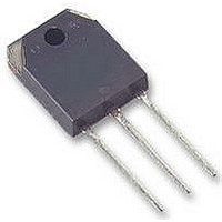
GT10Q101 Toshiba, GT10Q101 Datasheet - Page 2

GT10Q101
Manufacturer Part Number
GT10Q101
Description
IGBT, 1200V, TO-3P(N)
Manufacturer
Toshiba
Specifications of GT10Q101
Transistor Type
IGBT
Dc Collector Current
10A
Collector Emitter Voltage Vces
2.7V
Power Dissipation Max
140W
Collector Emitter Voltage V(br)ceo
1.2kV
Transistor Case Style
TO-3P
No. Of Pins
3
Current Ic
RoHS Compliant
Channel Type
N
Configuration
Single
Collector-emitter Voltage
1.2kV
Gate To Emitter Voltage (max)
±20V
Package Type
TO-3PN
Pin Count
3 +Tab
Mounting
Through Hole
Operating Temperature (max)
150C
Operating Temperature Classification
Military
Power Dissipation Pd
140W
Rohs Compliant
Yes
Svhc
No SVHC
Lead Free Status / Rohs Status
Not Compliant
Electrical Characteristics
Gate leakage current
Collector cut-off current
Gate-emitter cut-off voltage
Collector-emitter saturation voltage
Input capacitance
Switching time
Thermal resistance
Note1: Switching time measurement circuit and input/output waveforms
Note2: Switching loss measurement waveforms
-V
0
0
GE
GT10Q301
Characteristic
V
V
I
GE
CE
C
R
G
I
Turn-on time
Turn-off time
C
Rise time
Fall time
90%
E
L
off
V
CE
V
(Ta = = = = 25°C)
CC
V
V
Symbol
R
GE (OFF)
CE (sat)
I
I
C
th (j-c)
GES
CES
t
t
on
off
t
t
ies
r
f
10%
0
0
V
V
I
I
V
Inductive Load
V
V
C
C
GE
CE
CE
CC
GG
= 1 mA, V
= 10 A, V
V
V
I
= ±20 V, V
= 1200 V, V
= 50 V, V
= 600 V, I
E
= ±15 V, R
GE
CE
C
on
2
GE
t
Test Condition
CE
10%
d (off)
GE
10%
C
CE
= 15 V
= 5 V
G
GE
= 10 A
= 0, f = 1 MHz
= 75 W
¾
= 0
90%
= 0
t
off
t
f
90%
10%
(Note1)
Min
10%
10%
4.0
t
¾
¾
¾
¾
¾
¾
¾
¾
¾
d (on)
Typ.
0.07
0.30
0.16
0.50
600
2.1
t
¾
¾
¾
¾
t
on
r
90%
GT10Q101
2003-03-18
±500
0.32
0.89
Max
1.0
7.0
2.7
¾
¾
¾
10%
¾
°C/W
Unit
mA
nA
pF
ms
V
V


