SI5857DU-T1-GE3 Vishay, SI5857DU-T1-GE3 Datasheet - Page 2
SI5857DU-T1-GE3
Manufacturer Part Number
SI5857DU-T1-GE3
Description
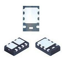
P CHANNEL MOSFET, -20V, 6A POWERPAK
Manufacturer
Vishay
Datasheet
1.SI5857DU-T1-GE3.pdf
(10 pages)
Specifications of SI5857DU-T1-GE3
Transistor Polarity
P Channel + Schottky Diode
Continuous Drain Current Id
6A
Drain Source Voltage Vds
-20V
On Resistance Rds(on)
100mohm
Rds(on) Test Voltage Vgs
12V
Configuration
Single Dual Drain
Resistance Drain-source Rds (on)
0.058 Ohms
Drain-source Breakdown Voltage
- 20 V
Gate-source Breakdown Voltage
+/- 12 V
Continuous Drain Current
5 A
Power Dissipation
2.3 W
Maximum Operating Temperature
+ 150 C
Mounting Style
SMD/SMT
Package / Case
PowerPAK ChipFET
Minimum Operating Temperature
- 55 C
Lead Free Status / RoHS Status
Lead free / RoHS Compliant


Si5857DU
Vishay Siliconix
Notes:
a. Package limited.
b. Surface Mounted on FR4 board.
c. t ≤ 5 s.
d. See Solder Profile (www.vishay.com/doc?73257). The PowerPAK ChipFET is a leadless package. The end of the lead terminal is exposed
e. Rework Conditions: manual soldering with a soldering iron is not recommended for leadless components.
f. Maximum under Steady State conditions for MOSFETS is 105 °C/W.
g. Maximum under Steady State conditions for Schottky is 110 °C/W.
www.vishay.com
2
THERMAL RESISTANCE RATINGS
Parameter
Maximum Junction-to-Ambient (MOSFET)
Maximum Junction-to-Case (Drain) (MOSFET)
Maximum Junction-to-Ambient (Schottky)
Maximum Junction-to-Case (Drain) (Schottky)
SPECIFICATIONS T
Parameter
Static
Drain-Source Breakdown Voltage
V
V
Gate-Source Threshold Voltage
Gate-Body Leakage
Zero Gate Voltage Drain Current
On-State Drain Current
Drain-Source On-State Resistance
Forward Transconductance
Dynamic
Input Capacitance
Output Capacitance
Reverse Transfer Capacitance
Total Gate Charge
Gate-Source Charge
Gate-Drain Charge
Gate Resistance
Turn-On Delay Time
Rise Time
Turn-Off Delay Time
Fall Time
Turn-On Delay Time
Rise Time
Turn-Off Delay Time
Fall Time
copper (not plated) as a result of the singulation process in manufacturing. A solder fillet at the exposed copper tip cannot be guaranteed and
is not required to ensure adequate bottom side solder interconnection. Rework Conditions: manual soldering with a soldering iron is not
recommended for leadless components.
DS
GS(th)
Temperature Coefficient
Temperature Coefficient
b
a
a
J
= 25 °C, unless otherwise noted
a
ΔV
b, g
Symbol
ΔV
R
b, f
V
GS(th)/TJ
I
t
t
t
t
I
I
C
V
DS(on)
C
GS(th)
D(on)
C
Q
Q
d(on)
d(off)
d(on)
d(off)
GSS
DSS
g
Q
R
DS/TJ
DS
oss
t
t
t
t
rss
iss
fs
gs
gd
r
r
f
f
g
g
V
V
V
I
V
I
DS
D
DS
D
DS
DS
≅ - 4 A, V
≅ - 4 A, V
t ≤ 5 s
t ≤ 5 s
= - 10 V, V
= - 10 V, V
= - 20 V, V
V
V
V
= - 10 V, V
V
V
V
V
V
V
V
DS
GS
DS
DS
GS
DS
DD
DD
DS
GS
Test Conditions
≤ - 5 V, V
= V
= - 4.5 V, I
= - 10 V, I
= 0 V, V
= - 10 V, R
= - 10 V, R
= 0 V, I
= - 20 V, V
= - 2.5 V, I
I
D
GEN
GEN
f = 1 MHz
GS
= - 250 µA
GS
GS
GS
GS
, I
= - 4.5 V, R
= - 10 V, R
D
= - 4.5 V, I
D
= - 10 V, I
GS
= 0 V, T
GS
= 0 V, f = 1 MHz
= - 250 µA
Symbol
= - 250 µA
D
D
D
L
L
GS
R
R
R
R
= ± 12 V
= - 3.6 A
= - 3.6 A
= - 4.5 V
= 2.5 Ω
= 2.5 Ω
= - 1 A
thJA
thJC
thJA
thJC
= 0 V
J
D
= 55 °C
D
g
g
= - 5 A
= 1 Ω
= - 5 A
= 1 Ω
Typical
9.5
43
49
13
Min.
- 0.6
- 20
- 20
S09-2111-Rev. D, 12-Oct-09
Maximum
0.048
0.081
Typ.
- 19
480
125
2.6
5.5
1.2
1.8
10
90
11
11
42
33
50
15
25
10
Document Number: 73696
9
5
55
12
61
16
± 100
0.058
0.100
Max.
- 1.5
- 10
8.5
- 1
17
20
65
50
75
10
25
40
20
°C/W
Unit
mV/°C
Unit
µA
nC
pF
ns
ns
V
V
A
Ω
S
Ω
Related parts for SI5857DU-T1-GE3
Image
Part Number
Description
Manufacturer
Datasheet
Request
R

Part Number:
Description:
MOSFET P-CH 20V 6A PPAK CHIPFET
Manufacturer:
Vishay
Datasheet:
Part Number:
Description:
P-channel 20-v D-s Mosfet With Schottky Diode
Manufacturer:
Vishay
Datasheet:
Part Number:
Description:
357-036-542-201 CARDEDGE 36POS DL .156 BLK LOPRO
Manufacturer:
Vishay
Datasheet:
Part Number:
Description:
357-036-542-201 CARDEDGE 36POS DL .156 BLK LOPRO
Manufacturer:
Vishay
Datasheet:
Part Number:
Description:
357-036-542-201 CARDEDGE 36POS DL .156 BLK LOPRO
Manufacturer:
Vishay
Datasheet:
Part Number:
Description:
357-036-542-201 CARDEDGE 36POS DL .156 BLK LOPRO
Manufacturer:
Vishay
Datasheet:
Part Number:
Description:
357-036-542-201 CARDEDGE 36POS DL .156 BLK LOPRO
Manufacturer:
Vishay
Datasheet:
Part Number:
Description:
357-036-542-201 CARDEDGE 36POS DL .156 BLK LOPRO
Manufacturer:
Vishay
Datasheet:
Part Number:
Description:
357-036-542-201 CARDEDGE 36POS DL .156 BLK LOPRO
Manufacturer:
Vishay
Datasheet:
Part Number:
Description:
357-036-542-201 CARDEDGE 36POS DL .156 BLK LOPRO
Manufacturer:
Vishay
Datasheet:
Part Number:
Description:
357-036-542-201 CARDEDGE 36POS DL .156 BLK LOPRO
Manufacturer:
Vishay
Datasheet:
Part Number:
Description:
357-036-542-201 CARDEDGE 36POS DL .156 BLK LOPRO
Manufacturer:
Vishay
Datasheet:
Part Number:
Description:
357-036-542-201 CARDEDGE 36POS DL .156 BLK LOPRO
Manufacturer:
Vishay
Datasheet:
Part Number:
Description:
357-036-542-201 CARDEDGE 36POS DL .156 BLK LOPRO
Manufacturer:
Vishay
Datasheet:
Part Number:
Description:
357-036-542-201 CARDEDGE 36POS DL .156 BLK LOPRO
Manufacturer:
Vishay
Datasheet: