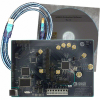
AD9910/PCBZ Analog Devices Inc, AD9910/PCBZ Datasheet

AD9910/PCBZ
Specifications of AD9910/PCBZ
Related parts for AD9910/PCBZ
AD9910/PCBZ Summary of contents
Page 1
... Factory tested and ready to use PACKAGE CONTENTS AD9910 evaluation board AD9910/PCBZ installation software CD USB cable Rev. 0 Evaluation boards are only intended for device evaluation and not for production purposes. Evaluation boards are supplied “as is” and without warranties of any kind, express, implied, or statutory including, but not limited to, any implied warranty of merchantability or fitness for a particular purpose ...
Page 2
... AD9910/PCBZ TABLE OF CONTENTS Features .............................................................................................. 1 Package Contents .............................................................................. 1 General Description ......................................................................... 1 Evaluation Board Block Diagram ................................................... 1 Evaluation Board Hardware ............................................................ 3 Requirements ................................................................................ 3 Setting Up the Evaluation Board ................................................ 3 Connectors .................................................................................... 3 Jumpers .......................................................................................... 3 Evaluation Board Layout ............................................................. 4 Evaluation Board Software .............................................................. 5 Installing the Software ................................................................. 5 Installing the Driver ..................................................................... 5 REVISION HISTORY 4/08—Revision 0: Initial Version ...
Page 3
... EVALUATION BOARD HARDWARE REQUIREMENTS To successfully use the evaluation board and run the software, the requirements listed in Table 1 must be met. Table 1. AD9910/PCBZ Requirements Item Requirement Operating Windows® 98/ME/2000/XP System Processor Pentium® later Memory 128 MB minimum Ports One USB port Clocking ...
Page 4
... AD9910/PCBZ EVALUATION BOARD LAYOUT STATUS PINS USB PORT Manual I/O Control Headers These pins provide the communication interface for the AD9910 when the part is under the command of an external controller (see Table 3 for correct jumper settings). Multidevice Synchronous Control These connections set up the AD9910 for multidevice synchronous operation ...
Page 5
... Select Programs, then the AD9910 Eval Software folder, and then AD9910 Eval Software to load the software. One of several status messages appears. These messages are discussed in further detail in the next section, Status Messages Upon Loading Software. Rev Page AD9910/PCBZ ...
Page 6
... AD9910/PCBZ Status Messages Upon Loading Software Once the AD9910 evaluation software is loaded, a green splash window appears. The status box within the splash window displays the status of the AD9910 evaluation software. Green writing in the status box indicates that the software has successfully loaded. ...
Page 7
... There are three drive strengths and a disable mode. PLL Lock indicates when the PLL valid lock state. If the PLL falls out of lock, the indicator light display illuminates. The Refresh button allows you to poll the AD9910 to refresh the PLL Lock flag. Rev Page AD9910/PCBZ ...
Page 8
... AD9910/PCBZ System Clock displays the operating frequency the DDS core (system). The value shown is derived from the values entered in the External Clock text box and the Multiplier spin box. Refer to the AD9910 data sheet for more information regarding clock modes and operation. ...
Page 9
... The Frequency spin box allows you to scroll through the different tuning words one bit at a time using the up and down arrows. Figure 7. Edit Output Frequency Pop-Up Dialog Box Rev Page AD9910/PCBZ ...
Page 10
... AD9910/PCBZ The Edit Phase Offset dialog box (see Figure 8) appears by double-clicking the Phase Offset text box in the Profiles window. The Edit Phase Offset window allows you to set individual bits in the phase offset word register. These bits can be typed in as decimal, hexadecimal, or binary in the Register Values area ...
Page 11
... VIEW WINDOWS To access additional windows, select View from the AD9910 Evaluation Software drop-down menu bar. Figure 10. Windows Accessed from View Menu Rev Page AD9910/PCBZ ...
Page 12
... AD9910/PCBZ OSK AND DIGITAL RAMP CONTROL To access the OSK & Digital Ramp Control window, select OSK Digital Ramp Control Window from the View drop-down menu. Digital Ramp Generator To use the digital ramp generator (DRG) function of the AD9910, select the Enable Digital Ramp Generator check box. Under Mode, select the frequency, phase, or amplitude to be generated ...
Page 13
... The No Error message box changes to Error and blinks when an error occurs. Using the Clear Error button, you can clear a sample error. Refer to the AD9910 data sheet for details on synchronizing multiple parts. Rev Page AD9910/PCBZ ...
Page 14
... AD9910/PCBZ RAM OPERATION Use of RAM on the AD9910 should not be attempted without using the AD9910 data sheet as a reference. The AD9910 data sheet contains detailed information on RAM operation. To use the RAM on the AD9910, select the Enable RAM check box on the Profiles window. This changes the appearance of the window from single-tone mode to RAM control mode ...
Page 15
... AD9910, LSB First or 3-Wire Mode. Auto Apply Note that when the Auto Apply check boxes in the DUT Signals (PA), DUT Signals (PE), and DUT Signals (CTL) areas are selected, the action is automatically taken without the need to click the Apply button. Rev Page AD9910/PCBZ ...
Page 16
... AD9910/PCBZ REGISTER MAP (SOFTWARE BUFFER) VALUES To access the Register Map (Software Buffer) Values window, select Register Map Values from the View drop-down menu (see Figure 10). Figure 16. Register Map (Software Buffer) Values window The Register Map (Software Buffer) Values window allows you to switch between the current values and the values that are loaded in the software buffer ...
Page 17
... ORDERING INFORMATION ORDERING GUIDE Model Description 1 AD9910/PCBZ Evaluation Board RoHS Compliant Part. ESD CAUTION Rev Page AD9910/PCBZ ...
Page 18
... AD9910/PCBZ NOTES Rev Page ...
Page 19
... NOTES Rev Page AD9910/PCBZ ...
Page 20
... AD9910/PCBZ NOTES ©2008 Analog Devices, Inc. All rights reserved. Trademarks and registered trademarks are the property of their respective owners. EB07481-0-4/08(0) Rev Page ...


