AD9910/PCBZ Analog Devices Inc, AD9910/PCBZ Datasheet - Page 6
AD9910/PCBZ
Manufacturer Part Number
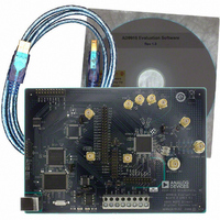
AD9910/PCBZ
Description
Direct Digital Synthesis Evaluation Board
Manufacturer
Analog Devices Inc
Series
AgileRF™r
Specifications of AD9910/PCBZ
Silicon Manufacturer
Analog Devices
Application Sub Type
Direct Digital Synthesizer
Kit Application Type
Clock & Timing
Silicon Core Number
AD9910
Kit Contents
Board
Design Resources
Synchronizing Multiple AD9910 1 GSPS Direct Digital Synthesizers (CN0121)
Main Purpose
Timing, Direct Digital Synthesis (DDS)
Embedded
No
Utilized Ic / Part
AD9910
Primary Attributes
14-Bit DAC, 32-Bit Tuning Word Width
Secondary Attributes
1GHz, Graphical User Interface
Lead Free Status / RoHS Status
Lead free / RoHS Compliant
Lead Free Status / RoHS Status
Lead free / RoHS Compliant, Lead free / RoHS Compliant
Other names
Q3335404


AD9910/PCBZ
Status Messages Upon Loading Software
Once the AD9910 evaluation software is loaded, a green splash
window appears. The status box within the splash window displays
the status of the AD9910 evaluation software. Green writing in
the status box indicates that the software has successfully loaded.
A successful load is followed by the status box disappearing.
A splash window with red writing in the status box indicates that
an error occurred. You can move the pointer over the red
writing, which allows you to scroll up and view the details and
possible cause of the error (see Figure 3).
Most status message errors can be resolved by checking jumper
settings, making sure that the evaluation board is powered up
correctly, and inspecting the USB port and cable connections.
When all power, USB port/cable connections, and jumper
settings are correct, an error may still appear if the clock input
Figure 4. Example of Window With the Evaluation Software Successfully Loaded
Rev. 0 | Page 6 of 20
is not properly configured. If any modifications to the board
were made, check the changes against the provided evaluation
board schematics for the AD9910. Check to make sure that the
clock input source is connected and properly configured.
Figure 3. Splash Window Error Status Box
Related parts for AD9910/PCBZ
Image
Part Number
Description
Manufacturer
Datasheet
Request
R


Part Number:
Description:
±1.7g Dual-Axis IMEMS Accelerometer Evaluation Board
Manufacturer:
Analog Devices Inc
Datasheet:

Part Number:
Description:
Inertial Sensor Evaluation System
Manufacturer:
Analog Devices Inc
Datasheet:
Part Number:
Description:
Manufacturer:
Analog Devices Inc
Datasheet:
Part Number:
Description:
Manufacturer:
Analog Devices Inc
Datasheet:
Part Number:
Description:
Manufacturer:
Analog Devices Inc
Datasheet:
Part Number:
Description:
Manufacturer:
Analog Devices Inc
Datasheet:
Part Number:
Description:
Manufacturer:
Analog Devices Inc
Datasheet:
Part Number:
Description:
Manufacturer:
Analog Devices Inc
Datasheet:
Part Number:
Description:
Manufacturer:
Analog Devices Inc
Datasheet:
Part Number:
Description:
Manufacturer:
Analog Devices Inc
Datasheet:
Part Number:
Description:
Manufacturer:
Analog Devices Inc
Datasheet:
Part Number:
Description:
Manufacturer:
Analog Devices Inc
Datasheet: