AD9910/PCBZ Analog Devices Inc, AD9910/PCBZ Datasheet - Page 12
AD9910/PCBZ
Manufacturer Part Number
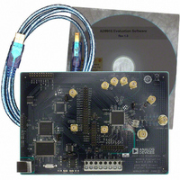
AD9910/PCBZ
Description
Direct Digital Synthesis Evaluation Board
Manufacturer
Analog Devices Inc
Series
AgileRF™r
Specifications of AD9910/PCBZ
Silicon Manufacturer
Analog Devices
Application Sub Type
Direct Digital Synthesizer
Kit Application Type
Clock & Timing
Silicon Core Number
AD9910
Kit Contents
Board
Design Resources
Synchronizing Multiple AD9910 1 GSPS Direct Digital Synthesizers (CN0121)
Main Purpose
Timing, Direct Digital Synthesis (DDS)
Embedded
No
Utilized Ic / Part
AD9910
Primary Attributes
14-Bit DAC, 32-Bit Tuning Word Width
Secondary Attributes
1GHz, Graphical User Interface
Lead Free Status / RoHS Status
Lead free / RoHS Compliant
Lead Free Status / RoHS Status
Lead free / RoHS Compliant, Lead free / RoHS Compliant
Other names
Q3335404


AD9910/PCBZ
OSK AND DIGITAL RAMP CONTROL
To access the OSK & Digital Ramp Control window, select OSK
Digital Ramp Control Window from the View drop-down menu.
Digital Ramp Generator
To use the digital ramp generator (DRG) function of the AD9910,
select the Enable Digital Ramp Generator check box. Under
Mode, select the frequency, phase, or amplitude to be
generated. The Auto Clear Digital Ramp Accum. check box
allows you to set the clear digital ramp accumulator bit when
the I/O update signal is applied or when there is a profile
change. The clear bit is then released.
The Clear Digital Ramp Accumulator check box allows you to
set and keep the digital ramp accumulator cleared until that bit
is cleared. The Load DRR @I/O Update box allows you to
reload the digital ramp rate when an I/O update is issued or
when there is a profile change.
Figure 11. OSK and Digital Ramp Control Window
Rev. 0 | Page 12 of 20
Sweep Frequency 0 and Sweep Frequency 1 are the starting
and stopping frequencies of the ramp. Note that this is frequency,
phase, or amplitude depending on which ramp generator is
selected. It is important that the value in the Sweep 0 register
is always less than the value in the Sweep 1 register.
Use the Rising Step Size and Falling Step Size check boxes to
set the step size of the rising or falling ramp. The unit for these
changes depending on what type of ramp is being generated.
The Rising Step Interval and Falling Step Interval are used to
set the time between each rising or falling step on the ramp.
This is in units of microseconds.
The No Dwell High and No Dwell Low boxes set the correspond-
ing bit functions in the register map. Use the Up, Down, and
Pause buttons at the bottom of the window to control the
direction or to pause the ramp. The Ramp Finished message
box lights up when the ramp is complete.
Related parts for AD9910/PCBZ
Image
Part Number
Description
Manufacturer
Datasheet
Request
R


Part Number:
Description:
±1.7g Dual-Axis IMEMS Accelerometer Evaluation Board
Manufacturer:
Analog Devices Inc
Datasheet:

Part Number:
Description:
Inertial Sensor Evaluation System
Manufacturer:
Analog Devices Inc
Datasheet:
Part Number:
Description:
Manufacturer:
Analog Devices Inc
Datasheet:
Part Number:
Description:
Manufacturer:
Analog Devices Inc
Datasheet:
Part Number:
Description:
Manufacturer:
Analog Devices Inc
Datasheet:
Part Number:
Description:
Manufacturer:
Analog Devices Inc
Datasheet:
Part Number:
Description:
Manufacturer:
Analog Devices Inc
Datasheet:
Part Number:
Description:
Manufacturer:
Analog Devices Inc
Datasheet:
Part Number:
Description:
Manufacturer:
Analog Devices Inc
Datasheet:
Part Number:
Description:
Manufacturer:
Analog Devices Inc
Datasheet:
Part Number:
Description:
Manufacturer:
Analog Devices Inc
Datasheet:
Part Number:
Description:
Manufacturer:
Analog Devices Inc
Datasheet: