AD9910/PCBZ Analog Devices Inc, AD9910/PCBZ Datasheet - Page 14
AD9910/PCBZ
Manufacturer Part Number
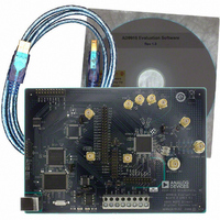
AD9910/PCBZ
Description
Direct Digital Synthesis Evaluation Board
Manufacturer
Analog Devices Inc
Series
AgileRF™r
Specifications of AD9910/PCBZ
Silicon Manufacturer
Analog Devices
Application Sub Type
Direct Digital Synthesizer
Kit Application Type
Clock & Timing
Silicon Core Number
AD9910
Kit Contents
Board
Design Resources
Synchronizing Multiple AD9910 1 GSPS Direct Digital Synthesizers (CN0121)
Main Purpose
Timing, Direct Digital Synthesis (DDS)
Embedded
No
Utilized Ic / Part
AD9910
Primary Attributes
14-Bit DAC, 32-Bit Tuning Word Width
Secondary Attributes
1GHz, Graphical User Interface
Lead Free Status / RoHS Status
Lead free / RoHS Compliant
Lead Free Status / RoHS Status
Lead free / RoHS Compliant, Lead free / RoHS Compliant
Other names
Q3335404


AD9910/PCBZ
RAM OPERATION
Use of RAM on the AD9910 should not be attempted without
using the AD9910 data sheet as a reference. The AD9910 data
sheet contains detailed information on RAM operation. To use
the RAM on the AD9910, select the Enable RAM check box on
the Profiles window. This changes the appearance of the
window from single-tone mode to RAM control mode.
Each RAM Segment section corresponds to a different profile.
RAM Segment 0 corresponds to Profile 0. Use the Beginning
Address and Final Address text boxes to set the beginning and
ending addresses for the RAM sweep. The Address Step Rate
sets the 16-bit address step rate value. The Mode Control drop-
down box sets the 3-bit RAM control word mode. See the
AD9910 data sheet for a complete description of the RAM
operating modes. The Zero Crossing check box sets the zero-
crossing bit. This bit is effective only in RAM mode using direct
switch. The No Dwell box sets the no-dwell high bit. This bit is
only effective when the RAM mode is in ramp-up.
Use the Activate area to switch between profiles. Use the
Internal Profile Control drop-down box to select the internal
profile control configurations. Refer to the AD9910 data sheet
for detailed information on the RAM internal profile control
modes. Use the RAM Data Type drop-down box to select the
Figure 13. Profiles Window When Using the RAM
Rev. 0 | Page 14 of 20
RAM playback destination. Refer to the AD9910 data sheet for
further details on the RAM playback destination bits.
Use the LOAD button to display the RAM I/O window.
RAM I/O
Figure 14. RAM I/O Window
Related parts for AD9910/PCBZ
Image
Part Number
Description
Manufacturer
Datasheet
Request
R


Part Number:
Description:
±1.7g Dual-Axis IMEMS Accelerometer Evaluation Board
Manufacturer:
Analog Devices Inc
Datasheet:

Part Number:
Description:
Inertial Sensor Evaluation System
Manufacturer:
Analog Devices Inc
Datasheet:
Part Number:
Description:
Manufacturer:
Analog Devices Inc
Datasheet:
Part Number:
Description:
Manufacturer:
Analog Devices Inc
Datasheet:
Part Number:
Description:
Manufacturer:
Analog Devices Inc
Datasheet:
Part Number:
Description:
Manufacturer:
Analog Devices Inc
Datasheet:
Part Number:
Description:
Manufacturer:
Analog Devices Inc
Datasheet:
Part Number:
Description:
Manufacturer:
Analog Devices Inc
Datasheet:
Part Number:
Description:
Manufacturer:
Analog Devices Inc
Datasheet:
Part Number:
Description:
Manufacturer:
Analog Devices Inc
Datasheet:
Part Number:
Description:
Manufacturer:
Analog Devices Inc
Datasheet:
Part Number:
Description:
Manufacturer:
Analog Devices Inc
Datasheet: