AD9910/PCBZ Analog Devices Inc, AD9910/PCBZ Datasheet - Page 9
AD9910/PCBZ
Manufacturer Part Number
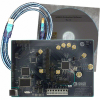
AD9910/PCBZ
Description
Direct Digital Synthesis Evaluation Board
Manufacturer
Analog Devices Inc
Series
AgileRF™r
Specifications of AD9910/PCBZ
Silicon Manufacturer
Analog Devices
Application Sub Type
Direct Digital Synthesizer
Kit Application Type
Clock & Timing
Silicon Core Number
AD9910
Kit Contents
Board
Design Resources
Synchronizing Multiple AD9910 1 GSPS Direct Digital Synthesizers (CN0121)
Main Purpose
Timing, Direct Digital Synthesis (DDS)
Embedded
No
Utilized Ic / Part
AD9910
Primary Attributes
14-Bit DAC, 32-Bit Tuning Word Width
Secondary Attributes
1GHz, Graphical User Interface
Lead Free Status / RoHS Status
Lead free / RoHS Compliant
Lead Free Status / RoHS Status
Lead free / RoHS Compliant, Lead free / RoHS Compliant
Other names
Q3335404


PROFILES WINDOW
The Profiles window allows you to change the different profile
settings easily. Figure 6 shows the Profiles window for using the
single-tone mode.
SINGLE-TONE MODE
Output Freq is used to set the frequency generated by the DDS.
The AD9910 generates a sine/cosine wave at this output
frequency.
Phase Offset controls the phase of the DDS output. This can be
changed from 0° to 360° with 16-bit resolution. The spin boxes
for phase offset are set to 1 bit by default. The phase offset
degree and number of bits can be changed to your preference by
typing in the text box and spin box, respectively
Amplitude SF digitally controls the amplitude of the carrier
from the DDS. This scalar has 14 bits of resolution. Note that
this can be used in conjunction with DAC Gain Ctrl in the
AUX DAC Control section (see Figure 5) to increase the
flexibility of the output amplitude. The spin boxes for amplitude
SF are set to 1 bit by default. The number of bits can be changed
to your preference by typing in the spin box.
Figure 6. Profile Control Window
Rev. 0 | Page 9 of 20
Data Entry Windows
The Edit output frequency dialog box (see Figure 7) appears by
double-clicking the Output Freq text box in the Profiles window.
The Edit output frequency window allows you to set individual
bits in the frequency tuning word register. These bits can be typed
in as decimal, hexadecimal, or binary format in the Tuning
Word Values area. This window also allows you to enter in a
tuning word and see the correct decimal, hexadecimal, or binary
representations for this word. The Frequency spin box allows
you to scroll through the different tuning words one bit at a
time using the up and down arrows.
Figure 7. Edit Output Frequency Pop-Up Dialog Box
AD9910/PCBZ
Related parts for AD9910/PCBZ
Image
Part Number
Description
Manufacturer
Datasheet
Request
R


Part Number:
Description:
±1.7g Dual-Axis IMEMS Accelerometer Evaluation Board
Manufacturer:
Analog Devices Inc
Datasheet:

Part Number:
Description:
Inertial Sensor Evaluation System
Manufacturer:
Analog Devices Inc
Datasheet:
Part Number:
Description:
Manufacturer:
Analog Devices Inc
Datasheet:
Part Number:
Description:
Manufacturer:
Analog Devices Inc
Datasheet:
Part Number:
Description:
Manufacturer:
Analog Devices Inc
Datasheet:
Part Number:
Description:
Manufacturer:
Analog Devices Inc
Datasheet:
Part Number:
Description:
Manufacturer:
Analog Devices Inc
Datasheet:
Part Number:
Description:
Manufacturer:
Analog Devices Inc
Datasheet:
Part Number:
Description:
Manufacturer:
Analog Devices Inc
Datasheet:
Part Number:
Description:
Manufacturer:
Analog Devices Inc
Datasheet:
Part Number:
Description:
Manufacturer:
Analog Devices Inc
Datasheet:
Part Number:
Description:
Manufacturer:
Analog Devices Inc
Datasheet: