AD9913/PCBZ Analog Devices Inc, AD9913/PCBZ Datasheet - Page 2
AD9913/PCBZ
Manufacturer Part Number
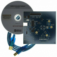
AD9913/PCBZ
Description
Eval Board
Manufacturer
Analog Devices Inc
Series
AgileRF™r
Datasheet
1.AD9913BCPZ.pdf
(32 pages)
Specifications of AD9913/PCBZ
Silicon Manufacturer
Analog Devices
Application Sub Type
Direct Digital Synthesizer
Kit Application Type
Clock & Timing
Silicon Core Number
AD9913
Kit Contents
Board
Tool / Board Applications
D/A Converter
Main Purpose
Timing, Direct Digital Synthesis (DDS)
Embedded
No
Utilized Ic / Part
AD9913
Primary Attributes
10-Bit DAC, 32-Bit Tuning Word Width
Secondary Attributes
250MHz, Graphical User Interface
Lead Free Status / RoHS Status
Lead free / RoHS Compliant


AD9913
TABLE OF CONTENTS
Features .............................................................................................. 1
Applications ....................................................................................... 1
General Description ......................................................................... 1
Functional Block Diagram .............................................................. 1
Revision History ............................................................................... 2
Specifications ..................................................................................... 3
Absolute Maximum Ratings ............................................................ 5
Pin Configuration and Function Descriptions ............................. 6
Typical Performance Characteristics ............................................. 8
Applications Circuits ...................................................................... 11
Theory of Operation ...................................................................... 12
Modes of Operation ....................................................................... 14
REVISION HISTORY
6/10—Rev. 0 to Rev. A
Added Digital Input Voltage to Table 2 ......................................... 5
Added Exposed Pad Notation to Figure 3 and Table 3 ................ 5
Changes to Programmable Modulus Mode Section .................. 14
Changes to Serial Programming Section ..................................... 22
Changes to Data Write Operation Section .................................. 24
Added Register Update (I/O Update) section and Figure 35 ... 25
Added Endnote 1 to Table 9 .......................................................... 26
Changes to Register Bit Descriptions Section and Bit 7
Description in Table 10 .................................................................. 28
Changes to Table 15 and Table 16 ................................................ 31
Added Exposed Pad Notation to Outline Dimensions ............. 32
10/07—Revision 0: Initial Version
Electrical Specifications ............................................................... 3
ESD Caution .................................................................................. 5
Equivalent Circuits ....................................................................... 5
DDS Core ..................................................................................... 12
Auxiliary Accumulator .............................................................. 13
10-Bit DAC .................................................................................. 13
I/O Port ........................................................................................ 13
Profile Selections ........................................................................ 13
Single Tone Mode ....................................................................... 14
Rev. A | Page 2 of 32
Clock Input (REF_CLK) ................................................................ 18
I/O Programming ........................................................................... 22
Register Map and Bit Descriptions .............................................. 26
Outline Dimensions ....................................................................... 32
Direct Switch Mode ................................................................... 14
Programmable Modulus Mode ................................................ 14
Linear Sweep Mode .................................................................... 14
REF_CLK Overview .................................................................. 18
Crystal-Driven REF_CLK ......................................................... 18
Direct-Driven REF_CLK ........................................................... 18
CMOS-Driven REF_CLK ......................................................... 18
Phase-Locked Loop (PLL) Multiplier ...................................... 18
PLL Lock Indication .................................................................. 19
Power-Down Features ................................................................ 21
Serial Programming ................................................................... 22
Parallel I/O Programming ......................................................... 23
Register Update (I/O Update) .................................................. 25
Register Map ............................................................................... 26
Register Bit Descriptions ........................................................... 28
Ordering Guide .......................................................................... 32
Related parts for AD9913/PCBZ
Image
Part Number
Description
Manufacturer
Datasheet
Request
R


Part Number:
Description:
±1.7g Dual-Axis IMEMS Accelerometer Evaluation Board
Manufacturer:
Analog Devices Inc
Datasheet:

Part Number:
Description:
Inertial Sensor Evaluation System
Manufacturer:
Analog Devices Inc
Datasheet:
Part Number:
Description:
Manufacturer:
Analog Devices Inc
Datasheet:
Part Number:
Description:
Manufacturer:
Analog Devices Inc
Datasheet:
Part Number:
Description:
Manufacturer:
Analog Devices Inc
Datasheet:
Part Number:
Description:
Manufacturer:
Analog Devices Inc
Datasheet:
Part Number:
Description:
Manufacturer:
Analog Devices Inc
Datasheet:
Part Number:
Description:
Manufacturer:
Analog Devices Inc
Datasheet:
Part Number:
Description:
Manufacturer:
Analog Devices Inc
Datasheet:
Part Number:
Description:
Manufacturer:
Analog Devices Inc
Datasheet:
Part Number:
Description:
Manufacturer:
Analog Devices Inc
Datasheet:
Part Number:
Description:
Manufacturer:
Analog Devices Inc
Datasheet: