AD9913/PCBZ Analog Devices Inc, AD9913/PCBZ Datasheet - Page 7
AD9913/PCBZ
Manufacturer Part Number
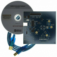
AD9913/PCBZ
Description
Eval Board
Manufacturer
Analog Devices Inc
Series
AgileRF™r
Datasheet
1.AD9913BCPZ.pdf
(32 pages)
Specifications of AD9913/PCBZ
Silicon Manufacturer
Analog Devices
Application Sub Type
Direct Digital Synthesizer
Kit Application Type
Clock & Timing
Silicon Core Number
AD9913
Kit Contents
Board
Tool / Board Applications
D/A Converter
Main Purpose
Timing, Direct Digital Synthesis (DDS)
Embedded
No
Utilized Ic / Part
AD9913
Primary Attributes
10-Bit DAC, 32-Bit Tuning Word Width
Secondary Attributes
250MHz, Graphical User Interface
Lead Free Status / RoHS Status
Lead free / RoHS Compliant


Pin No.
26
27
28
29
30
31
32
33
Mnemonic
PWR_DWN_CTL
IO_UPDATE
CS
SDIO(WR/RD)
SCLK/PCLK
ADR7/D7
ADR6/D6
Exposed Paddle
I/O
I
I
I
I/O
I
I/O
I/O
Input Clock for Serial and Parallel Port.
Description
External Power-Down, Digital Input (Active High). A high level on this pin initiates the currently
programmed power-down mode. See the Power-Down Features section for further details. If unused,
tie to ground.
I/O Update; Digital Input. A high on this pin indicates a transfer of the contents of the I/O buffers to the
corresponding internal registers.
Chip Select for Serial and Parallel Port. Digital input (active low). Bringing this pin low enables the
AD9913 to detect serial (SCLK) or parallel (PCLK) clock rising/falling edges. Bringing this pin high
causes the AD9913 to ignore input on the data pins.
Bidirectional Data Line for Serial Port Operation and Write/Read Enable for Parallel Port Operation.
Parallel Port Address Line 7 and Data Line 7.
Parallel Port Address Line 6 and Data Line 6.
The EPAD should be soldered to ground.
Rev. A | Page 7 of 32
AD9913
Related parts for AD9913/PCBZ
Image
Part Number
Description
Manufacturer
Datasheet
Request
R


Part Number:
Description:
±1.7g Dual-Axis IMEMS Accelerometer Evaluation Board
Manufacturer:
Analog Devices Inc
Datasheet:

Part Number:
Description:
Inertial Sensor Evaluation System
Manufacturer:
Analog Devices Inc
Datasheet:
Part Number:
Description:
Manufacturer:
Analog Devices Inc
Datasheet:
Part Number:
Description:
Manufacturer:
Analog Devices Inc
Datasheet:
Part Number:
Description:
Manufacturer:
Analog Devices Inc
Datasheet:
Part Number:
Description:
Manufacturer:
Analog Devices Inc
Datasheet:
Part Number:
Description:
Manufacturer:
Analog Devices Inc
Datasheet:
Part Number:
Description:
Manufacturer:
Analog Devices Inc
Datasheet:
Part Number:
Description:
Manufacturer:
Analog Devices Inc
Datasheet:
Part Number:
Description:
Manufacturer:
Analog Devices Inc
Datasheet:
Part Number:
Description:
Manufacturer:
Analog Devices Inc
Datasheet:
Part Number:
Description:
Manufacturer:
Analog Devices Inc
Datasheet: