AD9913/PCBZ Analog Devices Inc, AD9913/PCBZ Datasheet - Page 22
AD9913/PCBZ
Manufacturer Part Number
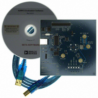
AD9913/PCBZ
Description
Eval Board
Manufacturer
Analog Devices Inc
Series
AgileRF™r
Datasheet
1.AD9913BCPZ.pdf
(32 pages)
Specifications of AD9913/PCBZ
Silicon Manufacturer
Analog Devices
Application Sub Type
Direct Digital Synthesizer
Kit Application Type
Clock & Timing
Silicon Core Number
AD9913
Kit Contents
Board
Tool / Board Applications
D/A Converter
Main Purpose
Timing, Direct Digital Synthesis (DDS)
Embedded
No
Utilized Ic / Part
AD9913
Primary Attributes
10-Bit DAC, 32-Bit Tuning Word Width
Secondary Attributes
250MHz, Graphical User Interface
Lead Free Status / RoHS Status
Lead free / RoHS Compliant


AD9913
I/O PROGRAMMING
SERIAL PROGRAMMING
The AD9913 serial port is a flexible, synchronous serial
communications port allowing an easy interface to many
industry standard microcontrollers and microprocessors.
The interface allows read/write access to all registers that
configure the AD9913. MSB first or LSB first transfer formats
are supported. The AD9913 serial interface port is configured
as a single pin I/O (SDIO), which allows a two-wire interface.
The AD9913 does not have a SDO pin for 3-wire operation.
With the AD9913, the instruction byte specifies read/write
operation and the register address. Serial operations on the
AD9913 occur only at the register level, not the byte level.
For the AD9913, the serial port controller recognizes the
instruction byte register address and automatically generates
the proper register byte address. In addition, the controller
expects that all bytes of that register are accessed. It is a
requirement that all bytes of a register be accessed during
serial I/O operations.
There are two phases to a communication cycle with the
AD9913. Phase 1 is the instruction cycle, which is the writing of
an instruction byte into the AD9913, coincident with the first
eight SCLK rising edges. The instruction byte provides the
AD9913 serial port controller with information regarding the
data transfer cycle, which is Phase 2 of the communication
cycle. The Phase 1 instruction byte defines whether the
SCLK
SCLK
SCLK
SDIO
SDIO
SDIO
CS
CS
CS
I
7
I
7
I
7
I
6
I
I
6
6
INSTRUCTION CYCLE
I
INSTRUCTION CYCLE
INSTRUCTION CYCLE
5
Figure 32. Two-Wire Serial Port Read Timing—Clock Stall High
I
5
I
5
Figure 30. Serial Port Writing Timing—Clock Stall Low
I
Figure 31. Serial Port Write Timing—Clock Stall High
4
I
4
I
4
I
3
I
3
I
3
I
2
I
2
I
2
Rev. A | Page 22 of 32
I
1
I
1
I
1
I
0
I
0
I
0
D
D
upcoming data transfer is read or write and the serial address of
the register being accessed.
The first eight SCLK rising edges of each communication cycle
are used to write the instruction byte into the AD9913. The
remaining SCLK edges are for Phase 2 of the communication
cycle. Phase 2 is the actual data transfer between the AD9913
and the system controller. The number of bytes transferred
during Phase 2 of the communication cycle is a function of the
register accessed. For example, when accessing the Control
Function Register 2, which is two bytes wide, Phase 2 requires
that two bytes be transferred. If accessing one of the profile
registers, which are six bytes wide, Phase 2 requires that six
bytes be transferred. After transferring all data bytes per the
instruction, the communication cycle is completed.
At the completion of any communication cycle, the AD9913
serial port controller expects the next eight rising SCLK edges
to be the instruction byte of the next communication cycle.
All data input to the AD9913 is registered on the rising edge
of SCLK. All data is driven out of the AD9913 on the falling
edge of SCLK. Figure 30 through Figure 32 illustrate the general
operation of serial ports.
Note that IO_UPDATE is not shown in Figure 30 and Figure 31.
The IO_UPDATE transfers the contents of the write sequence
to the active register. See the Register Update (I/O Update)
section.
7
7
D
O7
D
6
D
D
DATA TRANSFER CYCLE
6
O6
DATA TRANSFER CYCLE
D
5
DATA TRANSFER CYCLE
D
D
5
O5
D
4
D
D
4
O4
D
3
D
D
3
O3
D
2
D
D
2
O2
D
1
D
D
1
O1
D
0
D
D
O0
0
Related parts for AD9913/PCBZ
Image
Part Number
Description
Manufacturer
Datasheet
Request
R


Part Number:
Description:
±1.7g Dual-Axis IMEMS Accelerometer Evaluation Board
Manufacturer:
Analog Devices Inc
Datasheet:

Part Number:
Description:
Inertial Sensor Evaluation System
Manufacturer:
Analog Devices Inc
Datasheet:
Part Number:
Description:
Manufacturer:
Analog Devices Inc
Datasheet:
Part Number:
Description:
Manufacturer:
Analog Devices Inc
Datasheet:
Part Number:
Description:
Manufacturer:
Analog Devices Inc
Datasheet:
Part Number:
Description:
Manufacturer:
Analog Devices Inc
Datasheet:
Part Number:
Description:
Manufacturer:
Analog Devices Inc
Datasheet:
Part Number:
Description:
Manufacturer:
Analog Devices Inc
Datasheet:
Part Number:
Description:
Manufacturer:
Analog Devices Inc
Datasheet:
Part Number:
Description:
Manufacturer:
Analog Devices Inc
Datasheet:
Part Number:
Description:
Manufacturer:
Analog Devices Inc
Datasheet:
Part Number:
Description:
Manufacturer:
Analog Devices Inc
Datasheet: