AD6635BB Analog Devices Inc, AD6635BB Datasheet - Page 36
AD6635BB
Manufacturer Part Number
AD6635BB
Description
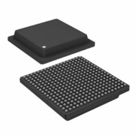
IC,RF/Baseband Circuit,CMOS,BGA,324PIN,PLASTIC
Manufacturer
Analog Devices Inc
Series
AD6635r
Datasheet
1.AD6635BBPCB.pdf
(60 pages)
Specifications of AD6635BB
Rohs Status
RoHS non-compliant
Rf Type
Cellular, CDMA2000, EDGE, GPRS, GSM
Number Of Mixers
1
Current - Supply
880mA
Voltage - Supply
3 V ~ 3.6 V
Package / Case
324-BGA
Frequency
-
Gain
-
Noise Figure
-
Secondary Attributes
-
Lead Free Status / RoHS Status
Available stocks
Company
Part Number
Manufacturer
Quantity
Price

Part Number:
AD6635BB
Manufacturer:
ADI/亚德诺
Quantity:
20 000


AD6635
10. When the SOFT_SYNC is addressed, the selected channels
11. If the user is providing external vectors, then the chip may
12. After a sufficient amount of time, the Channel BIST Signa-
CHIP SYNCHRONIZATION
Two types of synchronization can be achieved with the
AD6635. These are Start and Hop. Each is described in detail
below. The synchronization is accomplished with the use of a
shadow register and a holdoff counter. See Figure 33 for a
simplified schematic of the NCO shadow register and NCO
Frequency Holdoff counter to understand its basic operation.
Enabling the clock (AD6635 CLK) for the holdoff counter can
occur with either a Soft_Sync (via the Microport) or a pin sync
(via any of the four AD6635 SYNC Pins A, B, C, or D).
The four SYNC pins available on the AD6635 are common to
the entire chip, i.e., all 8 channels and all 4 AGCs. On the other
hand, the 4 Soft Sync channels specific to Channels 0 to 3 and
AGCs A and B are different from the 4 Soft Sync channels
specific to Channels 4 to 7 and AGCs C and D. This is the
effect of using different chip selects (CS0 and CS1) for these
different sets of sync channels. When using CS1 to program the
microport, the SOFT_SYNC register (external address 0x5)
and the SOFT SYNCs for Channels 4, 5, 6, and 7 are pro-
grammed. It should be noted that the SYNC pins are separate
from SOFT_SYNC Channels 0, 1, 2, and 3.
Start
Start refers to the startup of an individual channel, chip, or
multiple chips. If a channel is not used, it should be put in the
Sleep mode to reduce power dissipation. Following a hard reset
Figure 33. NCO Shadow Register and Holdoff Counter
will come out of the sleep mode and processing will occur.
ture registers 0xA5 and 0xA6 will contain a numeric value
that can be compared to the expected value for a known
good AD6635 with the exact same configuration. If the
values are the same, then there is a very low probability that
there is an error in the channel.
be brought out of Sleep mode by one of the other methods,
provided that either of the IEN inputs is inactive until the
channel is ready to accept data.
SOFT SYNC
PIN SYNC
ENABLE
ENABLE
AD6635
MICROPORT
CLK
FROM
I0
I31
REGISTER
MICRO
Q31
Q0
UPDATE HOLD OFF
NCO FREQUENCY
COUNTER
I0
I31
REGISTER
ENB
SHADOW
B15
B0
TC
Q31
Q0
FREQUENCY
I0
I31
REGISTER
NCO
Q31
Q0
TO
NCO
–36–
(low pulse on the AD6635 RESET pin), all channels are
placed into Sleep mode. Channels may also be manually put to
sleep by writing to the external address 0x3 controlling the
sleep function.
Start with No Sync
If no synchronization is needed to start multiple channels or
multiple AD6635s, the following method should be used to
initialize the device:
1. To program a channel, it must first be set to Sleep mode (bit
2. Set the Sleep bits low (Ext address 3). This enables the chan-
Start with Soft Sync
The AD6635 includes the ability to synchronize channels or
chips under microprocessor control. One action to synchronize
is the start of channels or chips. The Start Update Holdoff
counter (0x83) in conjunction with the Start bit and Sync bit
(Ext address 5) allow this synchronization. Basically, the Start
Update Holdoff counter delays the start of a channel(s) by its
value (number of AD6635 CLKs). The following method is
used to synchronize the start of multiple channels via micropro-
cessor control:
1. Set the appropriate channels to Sleep mode (a hard reset to
2. Note that the time from when the RDY (DTACK) pin goes
3. Write the Start Update Holdoff counter(s) (0x83) to the
4. Write the Start bit and the SYNC bit high (Ext address 5).
5. This starts the Start Update Holdoff counter counting
6. Note that Channels 0 to 3 and 4 to 7 will receive syncs
Start with Pin Sync
The AD6635 has four Sync Pins, A, B, C, and D, that can
provide for very accurate synchronization channels. Each chan-
nel can be programmed to listen to any of the four Sync pins.
Additionally, any or all channels can monitor a single Sync pin
or each can monitor a separate pin, providing complete flexibil-
ity in synchronization. Synchronization of Start with one of the
external signal is accomplished with the following method.
high, Ext address 3). All appropriate control and memory
registers (filter) are then loaded. The Start Update Holdoff
counter (0x83) should be set to 1:
nel. Note that when using external addresses, appropriate
chip selects should be used for the different channels. Chan-
nels 0–3 are started when CS0 is used, and Channels 4 –7
when CS1 is used.
the AD6635 RESET pin brings all four channels up in
Sleep mode).
high to when the NCO begins processing data is the contents
of the Start Update Holdoff Counter(s) (0x83) plus six mas-
ter clock cycles.
appropriate value (greater than 1 and less than 216 – 1). If
the chip(s) is not initialized, all other registers should be
loaded at this step.
down. The counter is clocked with the AD6635 CLK signal.
When it reaches a count of one, the Sleep bit of the appropri-
ate channel(s) is set low to activate the channel(s).
during different microport writes (separate syncs have to be
used for Channels 0 to 3 and 4 to 7). This time difference
for the two sets of channels (separate microport writes)
should be noted.
REV. 0
Related parts for AD6635BB
Image
Part Number
Description
Manufacturer
Datasheet
Request
R

Part Number:
Description:
±1.7g Dual-Axis IMEMS Accelerometer Evaluation Board
Manufacturer:
Analog Devices Inc
Datasheet:

Part Number:
Description:
Inertial Sensor Evaluation System
Manufacturer:
Analog Devices Inc
Datasheet:
Part Number:
Description:
Manufacturer:
Analog Devices Inc
Datasheet:
Part Number:
Description:
Manufacturer:
Analog Devices Inc
Datasheet:
Part Number:
Description:
Manufacturer:
Analog Devices Inc
Datasheet:
Part Number:
Description:
Manufacturer:
Analog Devices Inc
Datasheet:
Part Number:
Description:
Manufacturer:
Analog Devices Inc
Datasheet:
Part Number:
Description:
Manufacturer:
Analog Devices Inc
Datasheet:
Part Number:
Description:
Manufacturer:
Analog Devices Inc
Datasheet:
Part Number:
Description:
Manufacturer:
Analog Devices Inc
Datasheet:
Part Number:
Description:
Manufacturer:
Analog Devices Inc
Datasheet:
Part Number:
Description:
Manufacturer:
Analog Devices Inc
Datasheet:
Part Number:
Description:
Manufacturer:
Analog Devices Inc
Datasheet: