AD6635BB Analog Devices Inc, AD6635BB Datasheet - Page 50
AD6635BB
Manufacturer Part Number
AD6635BB
Description
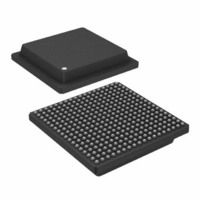
IC,RF/Baseband Circuit,CMOS,BGA,324PIN,PLASTIC
Manufacturer
Analog Devices Inc
Series
AD6635r
Datasheet
1.AD6635BBPCB.pdf
(60 pages)
Specifications of AD6635BB
Rohs Status
RoHS non-compliant
Rf Type
Cellular, CDMA2000, EDGE, GPRS, GSM
Number Of Mixers
1
Current - Supply
880mA
Voltage - Supply
3 V ~ 3.6 V
Package / Case
324-BGA
Frequency
-
Gain
-
Noise Figure
-
Secondary Attributes
-
Lead Free Status / RoHS Status
Available stocks
Company
Part Number
Manufacturer
Quantity
Price

Part Number:
AD6635BB
Manufacturer:
ADI/亚德诺
Quantity:
20 000


AD6635
To access the Output Port registers, the Access Input/Output
Control registers bit (Bit 5) in sleep register (0x3) should be
written high. The CAR (Channel Address Register, external
address 0x6) is then written with the address to the correct
Output Port register.
For Channels 0 to 3, Half-band Filters A and B, AGCs A and
B, and Output Ports A and B, Chip Select 0 (CS0) should be
used while programming using the microport. Similarly, for
Channels 4 to 7, Half-band Filters C and D, AGCs C and D,
and Output Ports C and D, Chip Select 1 (CS1) should be
used while programming using the microport.
Note: For all the registers in the Table XV, Output Ports A and
B (link or parallel) should be duplicated with Output Ports C
and D when Chip Select 1 (CS1) is used instead of (CS0) while
programming the microport. Similarly, half-band filters A and
B, and AGCs A and B should be duplicated with Half-band
Filters C and D, and AGCs C and D, respectively. Also Chan-
nels 0 to 3 should be duplicated with Channels 4 to 7 wherever
mentioned.
0x08 Port A Control Register
Bit 0 enables the use of the interpolating half-band filter corre-
sponding to Port A. Half-band Filter A can be used to
interleave the data streams of multiple channels and interpolate
by two, providing a maximum output data rate of 4 the chip
rate. It can be configured to listen to all four channels: Chan-
nels 0, 1, 2, 3; Channels 0, 1, 2; Channels 0, 1; or only Channel
0. Half-Band Filter A is bypassed when Bit 0 = 1, in which case
the outputs of the RCFs are sent directly to the AGC. The
channel data streams still are interleaved with the Half-Band
Filter bypassed, but they are not filtered and interpolated. The
maximum data rate from this configuration would be two times
the chip rate.
0x09 Port B Control Register
Bit 0 enables the use of the interpolating half-band filter cor-
responding to Port B. Half-band Filter B can be used to
interleave the data streams of multiple channels and interpolate
by 2, providing a maximum output data rate of 4 the chip
rate. It can be configured to listen to Channels 2 and 3; or only
Channel 2. Half-band Filter B is bypassed when Bit 0 = 1, in
which case the outputs of the RCFs are sent directly to the
AGC. The channel data streams still are interleaved with the
half-band filter bypassed, but they are not filtered and interpo-
lated. The maximum data rate from this configuration would be
two times the chip rate.
0x0A AGC A Control Register
This 8-bit register controls features of the AGC A. The bits are
defined below:
Bits 7–5 define the output word length of the AGC. The output
word can be 4–8, 10, 12, or 16 bits wide. The control register
bit representation to obtain different output word lengths is
given in the Memory Map table (Table XV).
Bit 4 of this register sets the mode of operation for the AGC.
When this bit is 0, the AGC tracks to maintain the output sig-
nal level, and when this bit is 1, the AGC tracks to maintain a
constant clipping error. Consult the AGC Mode section for
more details about these modes.
–50–
Bits 3–1 are used to configure the synchronization of the
AGC. The CIC decimator filter in the AGC can be synchro-
nized to an external sync signal to output an update sample
for the AGC error calculation and filtering. This way the
AGC gain changes can be synchronized to an external block
like a Rake receiver. Whenever an external sync signal is
received, the holdoff counter at 0x0B is loaded and begins to
count down. When the counter reaches 1, the CIC filter
dumps an update sample and starts working toward a new
update sample. The AGC can be initialized on each SYNC or
on only the first SYNC.
Bit 3 is used to issue a command to the AGC to SYNC immedi-
ately. If this bit is set, the CIC filter will update the AGC with a
new sample immediately and start operating toward the next
update sample. The AGC can be synchronized by the microport
control interface using this method.
Bit 2 is used to determine whether or not the AGC should
initialize on SYNC. When this bit is set, the CIC filter is
cleared and new values for CIC decimation, number of aver-
aging samples, CIC scale, signal gain ‘Gs,’ gain ‘K,’ and
pole parameter ‘P’ are loaded. When Bit 2 = 0, the above-
mentioned parameters are not updated and the CIC filter is
not cleared. In both cases, an AGC update sample is output
from the CIC filter and the decimator starts operating toward
the next output sample whenever a SYNC occurs.
Bit 1 is used to ignore repetitive synchronization signals. In
some applications, the synchronization signal may occur peri-
odically. If this bit is clear, each synchronization request will
resynchronize the AGC. If this bit is set, only the first occur-
rence will cause the AGC to synchronize and will update AGC
gain values periodically, depending on the decimation factor of
the AGC CIC filter.
Bit 0 is used to bypass the AGC section, when it is set. When
bypassed, the 16 MSBs coming into the AGC section are passed
to the output port (parallel/link). The output port will further
truncate the bit-width if 8-bit output is chosen.
0x0B AGC A Holdoff Counter
The AGC A Holdoff counter is loaded with the value written
to this address when either a Soft_SYNC or Pin_SYNC
comes into the channel. The counter begins counting down
so that when it reaches one, a SYNC is given to AGC A. This
SYNC may or may not initialize the AGC, as defined by the
control word. The AGC loop is updated with a new sample
from the CIC filter whenever a SYNC occurs. If this register
is written to 1, the AGC will be updated immediately when
the SYNC occurs. If this register is written to 0, the AGC
cannot be synchronized.
0x0C AGC A Desired Level
This 8-bit register contains the desired output power level or
desired clipping level, depending on the mode of operation. This
desired Request ‘R’ level can be set in dB from 0 dB to –23.99 dB
in steps of 0.094 dB. 8-bit binary floating-point representation is
used with a 2-bit exponent followed by a 6-bit mantissa. The
mantissa is in steps of 0.094 dB, and the exponent is in 6.02 dB
steps. For example 10’100101 represents 2
= 15.518 dB. It can also be calculated as (2 + (37/64))
15.518 dB.
6.02 + 37
REV. 0
6.02 =
0.094
Related parts for AD6635BB
Image
Part Number
Description
Manufacturer
Datasheet
Request
R

Part Number:
Description:
±1.7g Dual-Axis IMEMS Accelerometer Evaluation Board
Manufacturer:
Analog Devices Inc
Datasheet:

Part Number:
Description:
Inertial Sensor Evaluation System
Manufacturer:
Analog Devices Inc
Datasheet:
Part Number:
Description:
Manufacturer:
Analog Devices Inc
Datasheet:
Part Number:
Description:
Manufacturer:
Analog Devices Inc
Datasheet:
Part Number:
Description:
Manufacturer:
Analog Devices Inc
Datasheet:
Part Number:
Description:
Manufacturer:
Analog Devices Inc
Datasheet:
Part Number:
Description:
Manufacturer:
Analog Devices Inc
Datasheet:
Part Number:
Description:
Manufacturer:
Analog Devices Inc
Datasheet:
Part Number:
Description:
Manufacturer:
Analog Devices Inc
Datasheet:
Part Number:
Description:
Manufacturer:
Analog Devices Inc
Datasheet:
Part Number:
Description:
Manufacturer:
Analog Devices Inc
Datasheet:
Part Number:
Description:
Manufacturer:
Analog Devices Inc
Datasheet:
Part Number:
Description:
Manufacturer:
Analog Devices Inc
Datasheet: