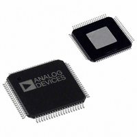
AD9773BSVRL Analog Devices Inc, AD9773BSVRL Datasheet - Page 2

AD9773BSVRL
Manufacturer Part Number
AD9773BSVRL
Description
IC,D/A CONVERTER,DUAL,12-BIT,CMOS,TQFP,80PIN
Manufacturer
Analog Devices Inc
Series
TxDAC®r
Datasheet
1.AD9773BSVZRL.pdf
(60 pages)
Specifications of AD9773BSVRL
Rohs Status
RoHS non-compliant
Settling Time
11ns
Number Of Bits
12
Data Interface
Serial, SPI™
Number Of Converters
2
Voltage Supply Source
Analog and Digital
Power Dissipation (max)
410mW
Operating Temperature
-40°C ~ 85°C
Mounting Type
Surface Mount
Package / Case
80-TQFP Exposed Pad, 80-eTQFP, 80-HTQFP, 80-VQFP
For Use With
AD9773-EBZ - BOARD EVALUATION AD9773
Lead Free Status / RoHS Status
AD9773
TABLE OF CONTENTS
Features .............................................................................................. 1
Applications....................................................................................... 1
Table of Contents .............................................................................. 2
General Description ......................................................................... 4
Specifications..................................................................................... 5
Absolute Maximum Ratings............................................................ 9
Pin Configuration and Function Descriptions........................... 10
Typical Performance Characteristics ........................................... 12
Terminology .................................................................................... 17
Functional Description .................................................................. 22
REVISION HISTORY
10/07—Rev. C to Rev. D
Updated Formatting ........................................................ Universal
Changes to Figure 32 .................................................................... 22
Functional Block Diagram .......................................................... 1
Revision History ........................................................................... 2
Product Highlights ....................................................................... 4
DC Specifications ......................................................................... 5
Dynamic Specifications ............................................................... 6
Digital Specifications ................................................................... 7
Digital Filter Specifications ......................................................... 8
Thermal Characteristics .............................................................. 9
ESD Caution.................................................................................. 9
Mode Control (Via SPI Port) .................................................... 18
Register Description................................................................... 20
Serial Interface for Register Control ........................................ 22
General Operation of the Serial Interface ............................... 22
Instruction Byte .......................................................................... 23
Serial Interface Port Pin Descriptions ..................................... 23
MSB/LSB Transfers..................................................................... 23
Notes on Serial Port Operation ................................................ 25
DAC Operation........................................................................... 25
1R/2R Mode ................................................................................ 26
Clock Input Configurations ...................................................... 27
Programmable PLL .................................................................... 27
Power Dissipation....................................................................... 29
Sleep/Power-Down Modes........................................................ 29
Rev. D | Page 2 of 60
Applying the Output Configurations........................................... 46
Evaluation Board ............................................................................ 48
Outline Dimensions ....................................................................... 58
Changes to Figure 108 .................................................................. 54
Updated Outline Dimensions ..................................................... 58
Changes to Ordering Guide......................................................... 58
Two-Port Data Input Mode ...................................................... 30
One-/Two-Port Input Modes.................................................... 30
PLL Enabled, Two-Port Mode .................................................. 30
DATACLK Inversion.................................................................. 31
DATACLK Driver Strength....................................................... 31
PLL Enabled, One-Port Mode .................................................. 31
ONEPORTCLK Inversion......................................................... 31
ONEPORTCLK Driver Strength.............................................. 32
IQ Pairing .................................................................................... 32
PLL Disabled, Two-Port Mode................................................. 32
PLL Disabled, One-Port Mode ................................................. 32
Digital Filter Modes ................................................................... 33
Amplitude Modulation.............................................................. 33
Modulation, No Interpolation .................................................. 34
Modulation, Interpolation = 2× ............................................... 35
Modulation, Interpolation = 4× ............................................... 36
Modulation, Interpolation = 8× ............................................... 37
Zero Stuffing ............................................................................... 38
Interpolating (Complex Mix Mode)........................................ 38
Operations on Complex Signals............................................... 38
Complex Modulation and Image Rejection of Baseband
Signals .......................................................................................... 39
Image Rejection and Sideband Suppression of Modulated
Carriers ........................................................................................ 41
Unbuffered Differential Output, Equivalent Circuit ............. 46
Differential Coupling Using a Transformer............................ 46
Differential Coupling Using an Op Amp................................ 47
Interfacing the AD9773 with the AD8345 Quadrature
Modulator.................................................................................... 47
Ordering Guide .......................................................................... 58


