AD9779A-EBZ Analog Devices Inc, AD9779A-EBZ Datasheet - Page 29
AD9779A-EBZ
Manufacturer Part Number
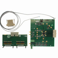
AD9779A-EBZ
Description
Dual 16B, 1.0 GSPS TxDAC
Manufacturer
Analog Devices Inc
Series
TxDAC®r
Datasheet
1.AD9776ABSVZ.pdf
(60 pages)
Specifications of AD9779A-EBZ
Design Resources
Interfacing ADL5370 to AD9779A Dual-Channel, 1 GSPS High Speed DAC (CN0016) Interfacing ADL5371 to AD9779A Dual-Channel, 1 GSPS High Speed DAC (CN0017) Interfacing ADL5372 to AD9779A Dual-Channel, 1 GSPS High Speed DAC (CN0018) Interfacing ADL5373 to AD9779A Dual-Channel, 1 GSPS High Speed DAC (CN0019) Interfacing ADL5374 to AD9779A Dual-Channel, 1 GSPS High Speed DAC (CN0020) Interfacing ADL5375 to AD9779A Dual-Channel, 1 GSPS High Speed DAC (CN0021)
Number Of Dac's
2
Number Of Bits
16
Outputs And Type
2, Differential
Sampling Rate (per Second)
1G
Data Interface
Serial
Dac Type
Current
Voltage Supply Source
Analog and Digital
Operating Temperature
-40°C ~ 85°C
Utilized Ic / Part
AD9779A
Lead Free Status / RoHS Status
Lead free / RoHS Compliant
Settling Time
-
Lead Free Status / RoHS Status
Lead free / RoHS Compliant


Register Name
PLL Control
Misc. Control
I DAC Control
AUX DAC1 Control
Q DAC Control
Register
Address
0x08
0x08
0x09
0x09
0x09
0x09
0x0A
0x0A
0x0C
0x0B
0x0C
0x0C
0x0E
0x0D
0x0E
0x0E
0x0E
0x10
0x0F
0x10
0x10
Bits
7:2
1:0
7
6:5
4:3
2:0
7:5
4:0
1:0
7:0
7
6
1:0
7:0
7
6
5
1:0
7:0
7
6
Parameter
PLL Band Select<5:0>
PLL VCO Drive<1:0>
PLL Enable
PLL VCO Divide Ratio<1:0>
PLL Loop Divide Ratio<1:0>
PLL Bias<2:0>
VCO Control Voltage<2:0>
(Read Only)
PLL Loop Bandwidth<4:0>
I DAC Gain Adjustment<9:8>
I DAC Gain Adjustment<7:0>
I DAC Sleep
I DAC Power-Down
Auxiliary DAC1 Data<9:8>
Auxiliary DAC1 Data<7:0>
Auxiliary DAC1 Sign
Auxiliary DAC1 Current
Direction
Auxiliary DAC1 Power-Down
Q DAC Gain Adjustment<9:8>
Q DAC Gain Adjustment<7:0>
Q DAC Sleep
Q DAC Power-Down
Rev. A | Page 29 of 60
Function
This sets the operating frequency range of the
VCO. For details, see Table 21.
Controls the signal strength of the VCO output. Set
to 11 for optimal performance.
0: PLL off, DAC sample clock is sourced directly by
the REFCLK input.
1: PLL on, DAC clock synthesized internally from
REFCLK input via PLL clock multiplier.
Sets the value of the VCO output divider which
determines the ratio of the VCO output frequency
to the DAC sample clock frequency, f
00: f
01: f
10: f
11: f
Sets the value of the DACCLK divider which
determines the ratio of the DAC sample clock
frequency to the REFCLK frequency, f
00: f
01: f
10: f
11: f
Controls VCO bias current. Set to 011 for optimal
performance.
000 to 111, proportional to voltage at VCO control
voltage input, readback only. A value of 011
indicates the VCO centered in its frequency range.
Controls the bandwidth of the PLL filter. Increasing
the value lowers the loop bandwidth. Set to 01111
for optimal performance.
I DAC 10-bit gain setting word. Bit 9 is the MSB and
Bit 0 is the LSB.
0: I DAC on
1: I DAC off
0: I DAC on
1: I DAC off
AUX DAC1 10-bit output current control word.
Magnitude of the AUX DAC current increases with
increasing value. Bit 9 is the MSB and Bit 0 is the LSB
0: AUX1_P active
1: AUX1_N active
0: source
1: sink
0: AUX DAC1 on
1: AUX DAC1 off
Q DAC 10-bit gain setting word. Bit 9 is the MSB
and Bit 0 is the LSB.
0: Q DAC on
1: Q DAC off
0: Q DAC on
1: Q DAC off
VCO
VCO
VCO
VCO
DACCLK
DACCLK
DACCLK
DACCLK
/f
/f
/f
/f
DACCLK
DACCLK
DACCLK
DACCLK
/f
/f
/f
/f
REFCLK
REFCLK
REFCLK
REFCLK
= 1
= 2
= 4
= 8
= 2
= 4
= 8
= 16
AD9776A/AD9778A/AD9779A
VCO
DACCLK
/f
DACCLK
/f
REFCLK
.
.
Default
111001
11
0
10
10
010
000
11111
01
11111001
0
0
00
00000000
0
0
0
01
11111001
0
0
Related parts for AD9779A-EBZ
Image
Part Number
Description
Manufacturer
Datasheet
Request
R

Part Number:
Description:
Dual 16B, 1.0 GSPS TxDAC
Manufacturer:
Analog Devices Inc
Datasheet:
Part Number:
Description:
BOARD EVALUATION FOR AD9779
Manufacturer:
Analog Devices Inc
Datasheet:
Part Number:
Description:
BOARD EVALUATION FOR AD9779
Manufacturer:
Analog Devices Inc
Datasheet:

Part Number:
Description:
±1.7g Dual-Axis IMEMS Accelerometer Evaluation Board
Manufacturer:
Analog Devices Inc
Datasheet:
Part Number:
Description:
Inertial Sensor Evaluation System
Manufacturer:
Analog Devices Inc
Datasheet:
Part Number:
Description:
Manufacturer:
Analog Devices Inc
Datasheet:
Part Number:
Description:
Manufacturer:
Analog Devices Inc
Datasheet:
Part Number:
Description:
Manufacturer:
Analog Devices Inc
Datasheet:
Part Number:
Description:
Manufacturer:
Analog Devices Inc
Datasheet:
Part Number:
Description:
Manufacturer:
Analog Devices Inc
Datasheet:
Part Number:
Description:
Manufacturer:
Analog Devices Inc
Datasheet:
Part Number:
Description:
Manufacturer:
Analog Devices Inc
Datasheet:
Part Number:
Description:
Manufacturer:
Analog Devices Inc
Datasheet: