ADUC7126BSTZ126-RL Analog Devices Inc, ADUC7126BSTZ126-RL Datasheet - Page 52
ADUC7126BSTZ126-RL
Manufacturer Part Number
ADUC7126BSTZ126-RL
Description
ARM7 With 12-Bit ADC & DACs, 128kB Flash
Manufacturer
Analog Devices Inc
Series
MicroConverter® ADuC7xxxr
Datasheet
1.ADUC7126BSTZ126.pdf
(104 pages)
Specifications of ADUC7126BSTZ126-RL
Core Processor
ARM7
Core Size
16/32-Bit
Speed
41.78MHz
Connectivity
EBI/EMI, I²C, SPI, UART/USART
Peripherals
POR, PWM, WDT
Number Of I /o
40
Program Memory Size
126KB (126K x 8)
Program Memory Type
FLASH
Ram Size
32K x 8
Voltage - Supply (vcc/vdd)
2.7 V ~ 3.6 V
Data Converters
A/D 12x12b, D/A 4x12b
Oscillator Type
Internal
Operating Temperature
-40°C ~ 125°C
Package / Case
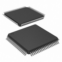
80-LQFP
Lead Free Status / RoHS Status
Lead free / RoHS Compliant
Eeprom Size
-
Lead Free Status / RoHS Status
Lead free / RoHS Compliant
Available stocks
Company
Part Number
Manufacturer
Quantity
Price
Company:

Part Number:
ADUC7126BSTZ126-RL
Manufacturer:
Analog Devices Inc
Quantity:
10 000


ADuC7124/ADuC7126
The endpoint nonlinearities conceptually illustrated in Figure 42
becomes worse as a function of output loading. Most of the
ADuC7124/ADuC7126 data sheet specifications assume a 5 kΩ
resistive load to ground at the DAC output. As the output is
forced to source or sink more current, the nonlinear regions at
the top or bottom (respectively) of Figure 42 become larger.
With larger current demands, this can significantly limit output
voltage swing.
References to ADC and the DACs
The ADC and DACs can be configured to use the internal V
or an external reference as a reference source. The internal V
must work with an external 0.47 µF capacitor.
Table 66. Reference Source Selection for the ADC and DACs
REFCON[0]
0
0
0
0
1
1
1
1
Note that if REFCON[1] = 1, the internal V
and the ADC cannot use the internal V
Figure 42. Endpoint Nonlinearities Due to Amplifier Saturation
AV
DD
– 100mV
100mV
AV
DACxCON[1:0]
00
01
10
11
00
01
10
11
DD
0x00000000
Description
ADC works with an external
reference. DACs are powered
down.
ADC works with an external
reference. DAC works with
DAC
Reserved.
ADC works with an external
reference. DACs work with
internal AV
ADC works with an internal V
DACs are powered down.
ADC works with an external
reference. DACs work with
DAC
ADC and DACs work with an
internal V
ADC works with an internal V
DACs work with an internal
AV
DD
REF
REF
.
.
.
REF
.
REF
DD
REF
.
.
0x0FFF0000
powers down
Rev. B | Page 52 of 104
REF
REF
REF
REF
.
.
Configuring DAC Buffers in Op Amp Mode
In op amp mode, the DAC output buffers are used as an op amp
with the DAC itself disabled.
If DACBCFG Bit 0 is set, ADC0 is the positive input to the op
amp, ADC1 is the negative input, and DAC0 is the output. In
this mode, the DAC should be powered down by clearing Bit 0
and Bit 1 of DAC0CON.
If DACBCFG Bit 1 is set, ADC2 is the positive input to the op
amp, ADC3 is the negative input, and DAC1 is the output. In
this mode, the DAC should be powered down by clearing Bit 0
and Bit 1 of DAC1CON.
If DACBCFG Bit 2 is set, ADC4 is the positive input to the op
amp, ADC5 is the negative input, and DAC2 is the output. In
this mode, the DAC should be powered down by clearing Bit 0
and Bit 1 of DAC2CON.
If DACBCFG Bit 3 is set, ADC8 is the positive input to the op
amp, ADC9 is the negative input, and DAC3 is the output. In
this mode, the DAC should be powered down by clearing Bit 0
and Bit 1 of DAC3CON.
DACBCFG Register
Name:
Address:
Default Value:
Access:
Table 67. DACBCFG MMR Bit Descriptions
Bit
[7:4]
3
2
1
0
The DACBCFG write sequence is as follows:
1.
2.
3.
Write Code 0x9A to Register DACBKEY1.
Write user value to Register DACBCFG.
Write Code 0x0C to Register DACBKEY2.
Description
Reserved. Always set to 0.
Set this bit to 1 to configure the DAC3 output
buffer in op amp mode.
Clear this bit for the DAC buffer to operate as
normal.
Set this bit to 1 to configure the DAC2 output
buffer in op amp mode.
Clear this bit for the DAC buffer to operate as
normal.
Set this bit to 1 to configure the DAC1 output
buffer in op amp mode.
Clear this bit for the DAC buffer to operate as
normal.
Set this bit to 1 to configure the DAC0 output
buffer in op amp mode.
Clear this bit for the DAC buffer to operate as
normal.
DACBCFG
0xFFFF0654
0x00
Read/write
Related parts for ADUC7126BSTZ126-RL
Image
Part Number
Description
Manufacturer
Datasheet
Request
R

Part Number:
Description:
Precision Analog Microcontroller, 12-Bit Analog I/O, Large Memory, ARM7TDMI MCU with Enhanced IRQ Handler
Manufacturer:
Analog Devices
Datasheet:

Part Number:
Description:
±1.7g Dual-Axis IMEMS Accelerometer Evaluation Board
Manufacturer:
Analog Devices Inc
Datasheet:

Part Number:
Description:
Inertial Sensor Evaluation System
Manufacturer:
Analog Devices Inc
Datasheet:
Part Number:
Description:
Manufacturer:
Analog Devices Inc
Datasheet:
Part Number:
Description:
Manufacturer:
Analog Devices Inc
Datasheet:
Part Number:
Description:
Manufacturer:
Analog Devices Inc
Datasheet:
Part Number:
Description:
Manufacturer:
Analog Devices Inc
Datasheet:
Part Number:
Description:
Manufacturer:
Analog Devices Inc
Datasheet:
Part Number:
Description:
Manufacturer:
Analog Devices Inc
Datasheet:
Part Number:
Description:
Manufacturer:
Analog Devices Inc
Datasheet:
Part Number:
Description:
Manufacturer:
Analog Devices Inc
Datasheet:
Part Number:
Description:
Manufacturer:
Analog Devices Inc
Datasheet:
Part Number:
Description:
Manufacturer:
Analog Devices Inc
Datasheet: