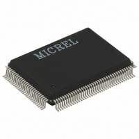
KSZ8995FQI Micrel Inc, KSZ8995FQI Datasheet - Page 30

KSZ8995FQI
Manufacturer Part Number
KSZ8995FQI
Description
5 Port 10/100 Switch With PHY And Frame Buffers ( )
Manufacturer
Micrel Inc
Datasheet
1.KSZ8995FQI.pdf
(79 pages)
Specifications of KSZ8995FQI
Number Of Primary Switch Ports
5
Internal Memory Buffer Size
64
Operating Supply Voltage (typ)
1.8/2.5/3.3V
Fiber Support
Yes
Integrated Led Drivers
Yes
Phy/transceiver Interface
MII/SNI
Data Rate (typ)
10/100Mbps
Vlan Support
Yes
Operating Temperature (max)
85C
Operating Temperature (min)
-40C
Pin Count
128
Mounting
Surface Mount
Jtag Support
No
Operating Temperature Classification
Industrial
Data Rate
100Mbps
Lead Free Status / RoHS Status
Lead free / RoHS Compliant
Other names
576-3300
Available stocks
Company
Part Number
Manufacturer
Quantity
Price
Part Number:
KSZ8995FQI
Manufacturer:
MICREL
Quantity:
20 000
Semptember 2008
The table 2 shows three connection ways,
The MII-P5 interface operates in PHY mode only, while the MII-SW interface operates in either MAC mode or PHY
mode for KSZ8995MA. The MII-SW interface operates in PHY mode only for KSZ8995FQ. These interfaces are
nibble-wide data interfaces and therefore run at 1/4 the network bit rate (not encoded). Additional signals on the
transmit side indicate when data is valid or when an error occurs during transmission. Likewise, the receive side has
indicators that convey when the data is valid and without physical layer errors. For half-duplex operation there is a
signal that indicates a collision has occurred during transmission.
Note that the signal MRXER is not provided on the MII-SW interface for PHY mode operation and the signal MTXER
is not provided on the MII-SW interface for MAC mode operation. Normally MRXER would indicate a receive error
coming from the physical layer device. MTXER would indicate a transmit error from the MAC device. These signals
are not appropriate for this configuration. For PHY mode operation, if the device interfacing with the KS8995MA/FQ
has an MRXER pin, it should be tied low. For MAC mode operation, if the device interfacing with the KS8995MA has
an MTXER pin, it should be tied low.
1. The first and second columns show the connections for external MAC and MII-SW PHY mode.
2. The fourth and fifth columns show the connections for external PHY and MII-SW MAC mode.
3. The second and fifth columns show the back to back connections for two MII-SWs of two devices.
External MAC
MRXDV
MRXER
MTXEN
MTXER
MTXD3
MTXD2
MTXD1
MTXD0
MRXD3
MRXD2
MRXD1
MRXD0
MCOL
MCRS
MRXC
MTXC
PHY Mode Connection
KS8995MA/FQ
SMRXD[3]
SMRXD[2]
SMRXD[1]
SMRXD[0]
SMTXD[3]
SMTXD[2]
SMTXD[1]
SMTXD[0]
SMRXDV
SMTXEN
SMTXER
Not used
SMRXC
SMTXC
Signal
SCOL
SCRS
Table 2. MII – SW Signals
Transmit data bit 3
Transmit data bit 2
Transmit data bit 1
Transmit data bit 0
Receive data valid
Collision detection
Receive data bit 3
Receive data bit 2
Receive data bit 1
Receive data bit 0
Transmit enable
Transmit clock
Transmit error
Receive clock
Carrier sense
Receive error
Description
30
External PHY
MRXDV
MRXER
MTXEN
MTXER
MRXD3
MRXD2
MRXD1
MRXD0
MTXD3
MTXD2
MTXD1
MTXD0
MCRS
MRXC
MTXC
MCOL
MAC Mode Connection
KS8995MA Only
SMRXD[3]
SMRXD[2]
SMRXD[1]
SMRXD[0]
SMTXD[3]
SMTXD[2]
SMTXD[1]
SMTXD[0]
SMRXDV
SMTXEN
SMTXER
Not used
SMRXC
SMTXC
Signal
SCOL
SCRS
M9999-091508


