H3DS-SL AC24-230/DC24-48 Omron, H3DS-SL AC24-230/DC24-48 Datasheet - Page 3
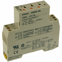
H3DS-SL AC24-230/DC24-48
Manufacturer Part Number
H3DS-SL AC24-230/DC24-48
Description
17.5mm TIMER DIN. MNT.
Manufacturer
Omron
Series
H3DSr
Specifications of H3DS-SL AC24-230/DC24-48
Relay Type
Integrated
Function
Programmable (Multi-Function)
Circuit
SPDT (1 Form C)
Delay Time
0.1 Sec ~ 120 Hrs
Output Type
Mechanical Relay
Contact Rating @ Voltage
5A @ 250VAC
Voltage - Supply
24 ~ 230VAC, 24 ~ 48VDC
Mounting Type
DIN Rail
Termination Style
Screw Terminal
Timing Adjustment Method
Screwdriver Slot
Timing Initiate Method
Input Voltage, Trigger Signal
Timing Range
0.1 s to 120 Hrs
Supply Voltage
24 V to 230 V
Lead Free Status / RoHS Status
Lead free / RoHS Compliant
Lead Free Status / RoHS Status
Lead free / RoHS Compliant
Other names
H3DSSLAC24230DC2448
Z2395
Z2395


H3DS
Specifications
I
Note: Can be mounted to 35-mm DIN Track with a plate thickness of 1 to 2.5 mm.
I
Note: When the time setting dial is set to “0” for any time scale, the output will operate instantaneously.
I
Note: 1. DC ripple rate: 20% max.
Item
Operating mode
Input type
Output type
External connections
Terminal block
Terminal screw tightening
torque
Mounting method
Attachment
Approved standards
Time scale display
0.1 s
1 s
0.1 m
1 m
0.1 h
1 h
10 h
Rated supply voltage
(See Notes 1 and 2.)
Operating voltage range
Power reset
Reset voltage
Power consumption (See Note 3.)
Voltage input
Control output
Ambient temperature
Ambient humidity
General
Time Ranges
Ratings
2. Since an inrush current of 0.4 A will occur when using the power supply voltage at 24 VDC, pay careful attention when turning
3. The power consumption is for mode A after the Timer counts the time-up time and for the AC input at 50 Hz. The power con-
on or off the power supply to the Timer with a solid-state output such as a sensor.
sumption of the H3DS-ML includes the input circuit with the B1 and A1 terminals short-circuited.
H3DS-ML@ @ @ @
A:
B:
B2: Repeat-cycle ON-start (Signal or Power)
C: Signal ON/OFF-delay
D: Signal OFF-delay
E:
G: Signal ON/OFF-delay
J:
Voltage input
Relay: SPDT
Screw terminal, cage clamp terminal
Screw terminal type: Clamps two 2.5-mm
Cage clamp terminal type: Clamps two 1.5-mm
0.98 N • m max.
DIN track mounting (See Note.)
Nameplate label
UL508, CSA C22.2 No.14
Conforms to EN61812-1, IEC60664-1 (VDE0110) 4 kV/2, VDE0106/P100
Output category according to IEC60947-5-1 (AC-13; 250 V 5 A/AC-14; 250 V 1 A/AC-15; 250 V 1 A/DC-13;
30 V 0.1 A/DC-14; 30 V 0.05 A)
Time range
0.1 to 1.2 s
1 to 12 s
0.1 to 1.2 min
1 to 12 min
0.1 to 1.2 h
1 to 12 h
10 to 120 h
ON-delay (Signal or Power)
Repeat-cycle OFF-start (Signal or Power)
Interval (Signal or Power)
One-shot (Signal or Power)
24 to 230 VAC (50/60 Hz)/24 to 48 VDC
85% to 110% of rated supply voltage
Minimum power-off time: 0.1 s
2.4 VAC/DC max.
AC: 32 VA max./3.0 W max. (typical: 30 VA/2.7 W) at 230 VAC
DC: 0.7 W max. (typical: 0.6 W) at 24 VDC
Max. permissible capacitance between inputs lines (terminals B1 and A2): 2,000 pF
Load connectable in parallel with inputs (terminals B1 and A1).
H-level: 20.4 to 253 VAC/20.4 to 52.8 VDC
L-level: 0 to 2.4 VAC/DC
Contact output: 5 A at 250 VAC with resistive load (cos φ = 1); 5 A at 30 VDC with resistive
load (cos φ = 1)
Operating: –10 ° C to 55 ° C (14 ° F to 131 ° F) with no icing
Storage: –25 ° C to 65 ° C (-13 ° F to 149 ° F) with no icing
Operating: 35% to 85%
14 VA max./2.2 W max. (typical: 13 VA/2.1 W) at 100 to 120 VAC
1.4 W max. (typical: 1.3 W) at 48 VDC
2
max. bar terminals without sleeves.
2
max. bar terminals without sleeves.
H3DS-SL@ @ @ @
A: ON-delay
B2: Repeat-cycle ON-start
E: Interval
J:
---
One-shot
H3DS-AL@ @ @ @
A: ON-delay (fixed)
H3DS
Related parts for H3DS-SL AC24-230/DC24-48
Image
Part Number
Description
Manufacturer
Datasheet
Request
R

Part Number:
Description:
G6S-2GLow Signal Relay
Manufacturer:
Omron Corporation
Datasheet:
Part Number:
Description:
Compact, Low-cost, SSR Switching 5 to 20 A
Manufacturer:
Omron Corporation
Datasheet:
Part Number:
Description:
Manufacturer:
Omron Corporation
Datasheet:
Part Number:
Description:
Manufacturer:
Omron Corporation
Datasheet:
Part Number:
Description:
Manufacturer:
Omron Corporation
Datasheet:
Part Number:
Description:
Manufacturer:
Omron Corporation
Datasheet:
Part Number:
Description:
Manufacturer:
Omron Corporation
Datasheet:
Part Number:
Description:
Manufacturer:
Omron Corporation
Datasheet: