H3DS-SL AC24-230/DC24-48 Omron, H3DS-SL AC24-230/DC24-48 Datasheet - Page 36
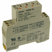
H3DS-SL AC24-230/DC24-48
Manufacturer Part Number
H3DS-SL AC24-230/DC24-48
Description
17.5mm TIMER DIN. MNT.
Manufacturer
Omron
Series
H3DSr
Specifications of H3DS-SL AC24-230/DC24-48
Relay Type
Integrated
Function
Programmable (Multi-Function)
Circuit
SPDT (1 Form C)
Delay Time
0.1 Sec ~ 120 Hrs
Output Type
Mechanical Relay
Contact Rating @ Voltage
5A @ 250VAC
Voltage - Supply
24 ~ 230VAC, 24 ~ 48VDC
Mounting Type
DIN Rail
Termination Style
Screw Terminal
Timing Adjustment Method
Screwdriver Slot
Timing Initiate Method
Input Voltage, Trigger Signal
Timing Range
0.1 s to 120 Hrs
Supply Voltage
24 V to 230 V
Lead Free Status / RoHS Status
Lead free / RoHS Compliant
Lead Free Status / RoHS Status
Lead free / RoHS Compliant
Other names
H3DSSLAC24230DC2448
Z2395
Z2395


H3DS-G
Precautions
I
Do not change the time scale or operating mode while the Timer is
in operation, or malfunction could result.
I
The H3DS Series has a transformerless power supply system.
Touching the input terminal while power is being supplied can
cause you to get an electrical shock.
Use the bar terminal for wiring the H3DS. Using a stranded-wire
terminal may cause a short-circuit due to a stray wire entering into
the Timer.
Both AC and DC power supplies can be connected to the power
input terminals without regarding polarity.
With the H3DS only, a DC power supply must be connected to the
power input terminals as designated according to the polarity of
the terminals.
A DC power supply can be connected if its ripple factor is 20% or
less and the mean voltage is within the rated operating voltage
range of the Timer.
Make sure that the voltage is applied within the specified range, or
the internal elements of the Timer may be damaged.
Connect the power supply voltage through a relay or switch in
such a way that the voltage reaches a fixed value at once or the
Timer may not be reset or a timer error could result.
I
If the load current is continuously being supplied to the Timer for a
long period of time, be sure to provide the mounting clearance as
shown in the figure below. If used under conditions other than
those specified below, the life of internal components may be
shortened due to an excessive rise in the internal temperature.
Switching Current vs. Ambient Temperature
(When Mounting Two or More H3DS Units Side-by-Side)
H3DS-GL@ @ @ @
(Measurement Condition: Input voltage of 230 VAC)
Setting Changes
Power Supplies
Installation
!WARNING
!WARNING
!WARNING
!WARNING
H3DS
t
H3DS
t: Mounting clearance (mm)
t
Mounting clearance:
50 mm min.
Mounting clearance:
10 mm
Mounting clearance:
5 mm
Mounting clearance:
0 mm
Load current (A)
H3DS
Maximum range of
operating ambient
temperature
DIN track
I
The H3DS as a built-in timer conforms to EN61812-1 provided
that the following conditions are satisfied:
The output section of the H3DS is provided only with basic
isolation. To ensure reinforced isolation required by the
EN61812-1, provide supplementary basic isolation on the
load side connected to the output.
The H3DS itself is designed according to the following:
• Overvoltage category III
• Pollution degree 2
On the above basis:
Operation parts on the front and bottom: Reinforced isolation
–With clearance of 5.5 mm and creepage distance of 5.5 mm
at 230 VAC
Output: Basic isolation
–With clearance of 3 mm and creepage distance of 3 mm at
230 VAC
I
When using the Timer in an area with excess electrical noise,
separate the Timer, wiring, and the equipment which gener-
ates the input signals as far as possible from the noise
sources. Shield the input signal wiring to prevent electrical
interference.
Organic solvents (such as paint thinner), as well as very
acidic or basic solutions, can damage the outer casing of the
Timer.
Do not use the Timer in places where it is exposed to dust,
corrosive gas, or direct sunlight.
When storing the Timer, make sure that the ambient tempera-
ture and humidity are within the rated values. Leave the Timer
at room temperature for at least three hours before using the
Timer if it has been stored at an ambient temperature of
–10 ° C or below.
I
If the Timer is mounted on a control board, remove the Timer
from the control board or short-circuit the circuitry of the
power board before carrying out a voltage withstand test
between the electrical circuitry and non-current-carrying metal
part of the Timer, in order to prevent the internal circuitry of
the Timer from damage.
Precautions for EN61812-1
Conformance
Environment
Voltage Withstand Test
H3DS-G
Related parts for H3DS-SL AC24-230/DC24-48
Image
Part Number
Description
Manufacturer
Datasheet
Request
R

Part Number:
Description:
G6S-2GLow Signal Relay
Manufacturer:
Omron Corporation
Datasheet:
Part Number:
Description:
Compact, Low-cost, SSR Switching 5 to 20 A
Manufacturer:
Omron Corporation
Datasheet:
Part Number:
Description:
Manufacturer:
Omron Corporation
Datasheet:
Part Number:
Description:
Manufacturer:
Omron Corporation
Datasheet:
Part Number:
Description:
Manufacturer:
Omron Corporation
Datasheet:
Part Number:
Description:
Manufacturer:
Omron Corporation
Datasheet:
Part Number:
Description:
Manufacturer:
Omron Corporation
Datasheet:
Part Number:
Description:
Manufacturer:
Omron Corporation
Datasheet: