H3DS-SL AC24-230/DC24-48 Omron, H3DS-SL AC24-230/DC24-48 Datasheet - Page 45
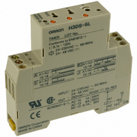
H3DS-SL AC24-230/DC24-48
Manufacturer Part Number
H3DS-SL AC24-230/DC24-48
Description
17.5mm TIMER DIN. MNT.
Manufacturer
Omron
Series
H3DSr
Specifications of H3DS-SL AC24-230/DC24-48
Relay Type
Integrated
Function
Programmable (Multi-Function)
Circuit
SPDT (1 Form C)
Delay Time
0.1 Sec ~ 120 Hrs
Output Type
Mechanical Relay
Contact Rating @ Voltage
5A @ 250VAC
Voltage - Supply
24 ~ 230VAC, 24 ~ 48VDC
Mounting Type
DIN Rail
Termination Style
Screw Terminal
Timing Adjustment Method
Screwdriver Slot
Timing Initiate Method
Input Voltage, Trigger Signal
Timing Range
0.1 s to 120 Hrs
Supply Voltage
24 V to 230 V
Lead Free Status / RoHS Status
Lead free / RoHS Compliant
Lead Free Status / RoHS Status
Lead free / RoHS Compliant
Other names
H3DSSLAC24230DC2448
Z2395
Z2395


H3DS-X
Installation of Cage Clamp Terminal Models
I
A flat-blade screwdriver should be used to install the cables.
Applicable Screwdriver
G Flat-blade, Parallel-tip, 2.5 mm diameter
Examples:FACOM AEF.2.5 × 75E
VESSEL No. 9900-(-)2.5 × 75
WAGO 210-119
WIHA 260/2.5 × 40
I
Applicable Wire Sizes
0.2 to 1.5 mm
Applicable Wire Type
Solid wires, stranded wires, flexible wires, or wires with ferrules
can be used.
(See note 1) < 1.8 ≤ Diameter D (mm) ≤ 3.0 (see note 2)
Conductor diameter d (mm) or length of sides a and b (mm) ≤ 1.6
Note: 1. If the overall diameter of the wire is less than 1.8 mm,
I
Use wires of the applicable sizes specified above. The length of
the exposed conductor should be 6 to 7 mm.
• Flat-blade, Parallel-tip
• Flat-blade, Flared-tip
Wires with Ferrules
Wiring
Tools
Applicable Wires
OK
Fig. 1 Exposed Conductor Length
2.5 dia.
2. If the overall diameter of the wire is over 2.8 mm, it will
do not insert the wire past the conductor. Refer to the
following diagrams.
be difficult to use double wiring.
2
, AWG24 to AWG16
Cannot be used.
6 to 7 mm
NG
2. Insert the exposed conductor into the wire connection
Wiring Precautions
Always insert the screwdriver straight into the hole, never at an
angle. The clamp spring may bend if the screwdriver is not
straight.
3. Pull out the screwdriver.
Do not move the screwdriver side to side in the clamp hole. The
clamp spring may bend if the screwdriver is moved sideways.
Wire
connection
holes
Release
holes
Fig. 2 Wire Connection Holes and Release Holes
Use the following procedure
1. Insert the specified screwdriver into the release hole locate
Fig. 3 Section A-A of Fig. 2
hole.
beside the wire connection hole where the wire is to be
inserted.
Wire connection hole
Release hole
Screwdriver
A
A
Insert
Insert
Insert
Pull out
H3DS-X
Related parts for H3DS-SL AC24-230/DC24-48
Image
Part Number
Description
Manufacturer
Datasheet
Request
R

Part Number:
Description:
G6S-2GLow Signal Relay
Manufacturer:
Omron Corporation
Datasheet:
Part Number:
Description:
Compact, Low-cost, SSR Switching 5 to 20 A
Manufacturer:
Omron Corporation
Datasheet:
Part Number:
Description:
Manufacturer:
Omron Corporation
Datasheet:
Part Number:
Description:
Manufacturer:
Omron Corporation
Datasheet:
Part Number:
Description:
Manufacturer:
Omron Corporation
Datasheet:
Part Number:
Description:
Manufacturer:
Omron Corporation
Datasheet:
Part Number:
Description:
Manufacturer:
Omron Corporation
Datasheet:
Part Number:
Description:
Manufacturer:
Omron Corporation
Datasheet: