HGTP2N120CN Fairchild Semiconductor, HGTP2N120CN Datasheet - Page 3
HGTP2N120CN
Manufacturer Part Number
HGTP2N120CN
Description
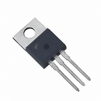
IGBT NPT N-CH 1200V 13A TO-220AB
Manufacturer
Fairchild Semiconductor
Datasheet
1.HGTP2N120CN.pdf
(9 pages)
Specifications of HGTP2N120CN
Igbt Type
NPT
Voltage - Collector Emitter Breakdown (max)
1200V
Vce(on) (max) @ Vge, Ic
2.4V @ 15V, 2.6A
Current - Collector (ic) (max)
13A
Power - Max
104W
Input Type
Standard
Mounting Type
Through Hole
Package / Case
TO-220-3 (Straight Leads)
Lead Free Status / RoHS Status
Lead free / RoHS Compliant
Available stocks
Company
Part Number
Manufacturer
Quantity
Price
Company:

Part Number:
HGTP2N120CN
Manufacturer:
IR
Quantity:
3 000
Company:
Part Number:
HGTP2N120CND
Manufacturer:
FAIRCHILD
Quantity:
12 500
Company:
Part Number:
HGTP2N120CNS
Manufacturer:
FAIRCHILD
Quantity:
12 500


HGTP2N120CN, HGT1S2N120CN Rev. C
Electrical Characteristics
Notes:
4. Values for two Turn-On loss conditions are shown for the convenience of the circuit designer. E
5. Turn-Off Energy Loss (E
t
t
t
t
E
E
E
t
t
t
t
E
E
E
R
d(ON)l
rl
d(OFF)l
fl
d(ON)l
rl
d(OFF)l
fl
diode is used in the test circuit and the diode is at the same T
current equals zero (I
produces the true total Turn-Off Energy Loss.
ON1
ON2
OFF
ON1
ON2
OFF
Symbol
θJC
Current Trun-On Delay Time
Current Rise Time
Curent Turn-Off Delay Time
Current Fall Time
Turn-On Energy (Note 4)
Turn-On Energy (Note 4)
Turn-Off Energy (Note 5)
Curent Turn-On Delay Time
Current Rise Time
Curent Turn-Off Delay Time
Current Fall Time
Turn-On Energy (Note 4)
Turn-On Energy (Note 4)
Turn-Off Energy (Note 5)
Thermal Resistance Junction to Case
CE
OFF
= 0A). All devices were tested per JEDEC Standard No. 24-1 Method for Measurement of Power Device Turn-Off Switching Loss. This test method
) is defined as the integral of the instantaneous power loss starting at the trailing edge of the input pulse and ending at the point where the collector
Parameter
T
C
= 25°C unless otherwise noted (Continued)
J
as the IGBT. The diode type is specified in Figure 18.
IGBT and Diode at T
I
V
V
R
L = 5mH
Test Circuit (Figure 18)
IGBT and Diode at T
I
V
V
R
L = 5mH
Test Circuit (Figure 18)
CE
CE
CE
GE
CE
GE
G
G
= 51Ω
= 51Ω
= 2.6A
= 2.6A
= 960V
= 960V
= 15V
= 15V
3
Test Conditions
ON1
is the turn-on loss of the IGBT only. E
J
J
= 25°C
= 150°C
Min. Typ. Max. Units
-
-
-
-
-
-
-
-
-
-
-
-
-
-
-
ON2
205
260
425
355
225
360
800
530
is the turn-on loss when a typical
25
21
11
96
11
96
-
1100
1.20
220
320
590
390
240
420
580
15
15
30
25
www.fairchildsemi.com
-
-
°C/W
ns
ns
ns
ns
µJ
µJ
µJ
ns
ns
ns
ns
µJ
µJ
µJ
Related parts for HGTP2N120CN
Image
Part Number
Description
Manufacturer
Datasheet
Request
R

Part Number:
Description:
Fairchild Semiconductor [IGBT MODULE]
Manufacturer:
Fairchild Semiconductor
Datasheet:

Part Number:
Description:
Discrete Semiconductor Modules
Manufacturer:
Fairchild Semiconductor
Part Number:
Description:
Discrete Semiconductor Modules
Manufacturer:
Fairchild Semiconductor
Part Number:
Description:
This N-Channel MOSFET is produced using Fairchild Semiconductor’s advanced Power Trench® process
Manufacturer:
Fairchild Semiconductor
Datasheet:
Part Number:
Description:
This N-Channel MOSFET is produced using Fairchild Semiconductor’s advanced Power Trench® process
Manufacturer:
Fairchild Semiconductor
Datasheet:
Part Number:
Description:
This N-Channel MOSFET is produced using Fairchild Semiconductor’s advanced PowerTrench® process
Manufacturer:
Fairchild Semiconductor
Datasheet:
Part Number:
Description:
This N-Channel MOSFET is produced using Fairchild Semiconductor’s advanced PowerTrench® process
Manufacturer:
Fairchild Semiconductor
Datasheet:
Part Number:
Description:
This N-Channel MOSFET is produced using Fairchild Semiconductor’s advanced Power Trench® process
Manufacturer:
Fairchild Semiconductor
Datasheet:
Part Number:
Description:
This N-Channel logic Level MOSFETs are produced using Fairchild Semiconductor‘s advanced Power Trench® process that has been special tailored to minimize the on-state resistance and yet maintain superior switching performance
Manufacturer:
Fairchild Semiconductor
Datasheet:
Part Number:
Description:
This N-Channel MOSFET is produced using Fairchild Semiconductor’s advanced Power Trench® process
Manufacturer:
Fairchild Semiconductor
Datasheet:
Part Number:
Description:
This N-Channel SyncFET™ is produced using Fairchild Semiconductor’s advanced PowerTrench® process
Manufacturer:
Fairchild Semiconductor
Datasheet:
Part Number:
Description:
This N-Channel SyncFET™ is produced using Fairchild Semiconductor’s advanced PowerTrench® process
Manufacturer:
Fairchild Semiconductor
Datasheet:
Part Number:
Description:
This N-Channel SyncFET™ is produced using Fairchild Semiconductor’s advanced PowerTrench® process
Manufacturer:
Fairchild Semiconductor
Datasheet:
Part Number:
Description:
This N-Channel logic Level MOSFETs are produced using Fairchild Semiconductor‘s advanced Power Trench® process that has been special tailored to minimize the on-state resistance and yet maintain superior switching performance
Manufacturer:
Fairchild Semiconductor
Datasheet:
Part Number:
Description:
This N-Channel MOSFET is produced using Fairchild Semiconductor’s advanced Power Trench® process that has been especially tailored to minimize the on-state resistance and yet maintain superior switching performance
Manufacturer:
Fairchild Semiconductor
Datasheet: