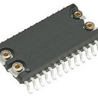
M48T86MH1 STMicroelectronics, M48T86MH1 Datasheet - Page 19

M48T86MH1
Manufacturer Part Number
M48T86MH1
Description
Real Time Clock USE 511-M48T86MH1E
Manufacturer
STMicroelectronics
Datasheet
1.M48T86MH1.pdf
(36 pages)
Specifications of M48T86MH1
Function
Clock, Calendar, Interrupt, Alarm
Rtc Memory Size
128 B
Supply Voltage (max)
5.5 V
Supply Voltage (min)
4.5 V
Maximum Operating Temperature
+ 70 C
Minimum Operating Temperature
0 C
Mounting Style
SMD/SMT
Rtc Bus Interface
Multiplexed
Package / Case
SO-28
Time Format
HH:MM:SS, Binary
Date Format
DW:DM:M:Y, Binary
Lead Free Status / RoHS Status
Lead free / RoHS Compliant
Available stocks
Company
Part Number
Manufacturer
Quantity
Price
Company:
Part Number:
M48T86MH1
Manufacturer:
CARTYS
Quantity:
2 585
Part Number:
M48T86MH1
Manufacturer:
ST
Quantity:
20 000
M48T86
3.10
3.10.1
3.10.2
3.10.3
Table 5.
Figure 9.
BIT7
UIP
UIP
Register A
UIP update in progress
The Update in Progress (UIP) bit is a status flag that can be monitored. When the UIP bit is
'1,' the update transfer will soon occur (see
will not occur for at least 244 µs. The time, calendar, and alarm information in RAM is fully
available for access when the UIP bit is '0.' The UIP bit is “Read only” and is not affected by
RST. Writing the SET bit in Register B to a '1' inhibits any update transfer and clears the UIP
Status bit.
OSC0, OSC1, OSC2 oscillator control
These three bits are used to control the oscillator and reset the countdown chain. A pattern
of “010” enables operation by turning on the oscillator and enabling the divider chain. A
pattern of 11X turns the oscillator on, but keeps the frequency divider disabled. When “010”
is written, the first update begins after 500 ms.
RS3, RS2, RS1, RS0
These four rate-selection bits select one of the 13 taps on the 15-stage divider or disable the
divider output. The tap selected may be used to generate an output square wave (SQW pin)
and/or a periodic interrupt. The user may do one of the following:
1.
or
2.
or
3.
or
4.
Table 4 on page 18
may be chosen with the RS bits. These four READ/WRITE bits are not affected by RST.
Register A MSB
Update period timing and UIP
OSC2
BIT6
Enable the interrupt with the PIE bit;
Enable the SQW output with the SQWE bit;
Enable both at the same time and same rate;
Enable neither.
OSC1
BIT5
lists the periodic interrupt rates and the square wave frequencies that
OSC0
BIT4
UPDATE PERIOD (1sec)
Figure
BIT3
RS3
9). When UIP is a '0,' the update transfer
tBUC
BIT2
RS2
tUC
BIT1
RS1
Clock operations
AI01651
BIT0
RS0
19/36


