9015 JEWELL / MODUTEC, 9015 Datasheet
9015
Specifications of 9015
Available stocks


9015 Summary of contents
Page 1
... Triplett Corporation One Triplett Drive Bluffton, OH 45817 800-TRIPLETT FAX: 419-358-7956 www.triplett.com © Triplett Corporation All Rights Reserved TRIPLETT Model 9015-A Digital Multimeter Instruction Manual ...
Page 2
... Accessories 11. Warranty 1: INTRODUCTION The Triplett Model 9015 1/2 digit, high reliability, handheld Digital Mul- timeter with a 1.15" high Liquid Crystal Display. At its core is an LSI (Large Scale Integration) integrated circuit which uses dual slope A/D conversion for stability and accuracy. The meter can measure AC and DC Voltage and Current, Resis- tance, Transistor gain, Diode voltage drop, Continuity, Capacitance, Temperature, and Frequency ...
Page 3
Do not use this meter with its case open, or with parts removed. Doing so may damage the meter and/or injure the user. 2.4 When using this meter in schools and workshops, responsible teachers or skilled personnel must control ...
Page 4
Do not exceed the maximum voltage or current limitations of the meter (see product specifications). Doing so may damage the meter and/or injure the user. 2.15 Do not apply voltage or current to the input of the meter when ...
Page 5
Do not use the meter if either the meter or the test leads are wet, either from exposure to the weather, or after cleaning the case of the meter. Doing so may cause injury to the user. 2.27 Do ...
Page 6
When you use the meter to check a high-voltage circuit, do not try to connect both test leads at once. Instead, clip one probe to the neutral or ground lead of the circuit (usually a bare, green, or white ...
Page 7
Avoid usage near strong RF fields (radio or television transmitters, walkie talkies, cellular phones, etc.). The meter may display readings that are in error, causing the user to misinterpret the hazards present. For example, the meter may indicate a ...
Page 8
INTERNATIONAL SYMBOLS The following International Symbols may be used in this manual and on the case of the meter to identify, caution, or warn the user of important product limitations or important operational procedures that must be followed to ...
Page 9
SPECIFICATIONS Display: 1.15" (29mm) high LCD Display Resolution: 2000 counts, 0000 to 1999 Overrange Indication: First digit displays “1”, remaining digits are blank Measurement Rate measurements per second Low Battery Annunciator: Operating Conditions: Temperature ...
Page 10
Note: a) The following accuracy specifications are valid at 73 degrees F ± 9 degrees (23 degrees C, ± 5 degrees C), Relative Humidity less than 75% b) The specifications are in the form “ ± reading ...
Page 11
...
Page 12
2µ µ ...
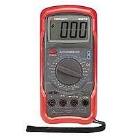
Page 13
... FRONT PANEL Liquid Crystal Display 2) POWER Button 3) Rotary Function / Range Switch 4) Capacitance Socket 5) Holster 6) HOLD Button 7) Thermocouple Input Jack 8) Transistor Socket 9) Input Jacks ...
Page 14
... Failure to observe this precaution may result in damage to 7.2 Auto Power Off: The 9015-A has Auto Power Off. This power saving feature automatically turns the meter off minutes after turning it on...... thereby extending battery life. ...
Page 15
Set the RANGE switch voltage is unknown, set the RANGE switch to the highest V If the input voltage is higher than the previously stated limits, do not attempt to measure! 7.3.3 Connect the test probes ...
Page 16
Connect the test probes to circuit being measured. The LCD will display the AC voltage. 7.4.4 If the display indicates overrange, i.e. “1- - -”, disconnect the test probes from the circuit and rotate the RANGE switch to the ...
Page 17
If the display indicates overrange, i.e. “1- - -”, disconnect the test probes from the circuit and reconnect the red test lead to the 10A jack. Set the RANGE switch to the 10A the circuit. Read the value from ...
Page 18
If the display indicates overrange, i.e. “1- - -”, disconnect the test probes from the circuit and reconnect the red test lead to the 10A jack. Set the RANGE switch to the 10 A circuit. Read the value from ...
Page 19
Notes: a) The 2M, 20M, and 200M ranges require several seconds to stabilize. b) The 200M range reads 10 LSD high. To obtain an accurate reading, subtract 10 LSD from the indicated value on the LCD obtain the ...
Page 20
Set the RANGE switch to the Diode Test / Continuity Beeper “ ” range. 7.9.3 Connect the test probes to the device or circuit to be tested. To test a simple diode, connect the red test probe to the ...
Page 21
Measuring Temperature: Do not attempt to measure the temperature of any surface that is electrically “live”. Failure to observe this precaution 7.11.1 Remove the test leads from the input jacks of the meter. 7.11.2 Set the RANGE switch to ...
Page 22
Notes the 2nF range, the meter will indicate residual capacitance without a capacitor inserted into the Cx socket. This is usually less than 0.020nF the capacitor to be measured is too large to insert into the ...
Page 23
... USING THE HOLSTER A protective holster is provided with the Model 9015-A. This vinyl holster pro- vides a measure of protection from the everyday rigors that products of this type are often subjected to. Molded into the holster are two holders for the test probes. When not in use, the test leads can be coiled around the meter and the probes snapped into these holders ...
Page 24
... MAINTENANCE Your Triplett Model 9015-A DMM is a precision measuring instrument and, when used as described in this manual, should not require maintenance. However, periodic calibration of the meter will insure that it is accurate and per- forming in accordance with its design specifications. A one year calibration inter- val is suggested ...
Page 25
Remove the 9 volt battery and replace with a fresh battery (PN 37-48). 9.1.5 Carefully install the fresh battery back into the meter, making sure that the battery wires will not be pinched when the case of the meter ...
Page 26
... Holster (Triplett PN 10-4281) Instruction Manual (Triplett PN 84-853) 10.2 Replacement Fuse 200mA/250V FAST 20mm (Triplett PN 3207-90) 10.3 Optional Carrying Case An optional carrying case is available for the 9015-A. It’s constructed of Cordura, with a Velcro secured flap, a belt loop on the back, and a padded interior. (Triplett PN 10-4275) 25 ...
Page 27
... Our obligation under this warranty is limited to repairing, replacing, or making refund on any instrument or test equipment which proves to be defective within three years from the date of original purchase. This warranty does not apply to any of our products which have been repaired or altered ...