9015 JEWELL / MODUTEC, 9015 Datasheet - Page 20
9015
Manufacturer Part Number
9015
Description
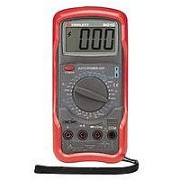
MULTIMETER DIGITAL HANDHELD, 3-1/2 DIGIT
Manufacturer
JEWELL / MODUTEC
Datasheet
1.9015.pdf
(27 pages)
Specifications of 9015
Dmm Type
Handheld
Voltage Measuring Range Dc
1000
Voltage Measuring Range Ac
750
Current Measuring Range Dc
2mA To 10A
Current Measuring Range Ac
20mA To 10A
Lead Free Status / RoHS Status
na
Available stocks
Company
Part Number
Manufacturer
Quantity
Price

Part Number:
9015
Manufacturer:
CJ/长电
Quantity:
20 000
Company:
Part Number:
90151-2114
Manufacturer:
MOLEX
Quantity:
12 000
Company:
Part Number:
90151-2116
Manufacturer:
MOLEX
Quantity:
42 144
Company:
Part Number:
90151-2116
Manufacturer:
MOLEX
Quantity:
35 000
Company:
Part Number:
901512104
Manufacturer:
Molex, LLC
Quantity:
201
Company:
Part Number:
901512106
Manufacturer:
Molex, LLC
Quantity:
184


7.9.2 Set the RANGE switch to the Diode Test / Continuity Beeper
7.9.3 Connect the test probes to the device or circuit to be tested. To test a
Note: The reading displayed on the LCD is an accurate indication of the voltage
7.10 Measuring Transistor hFE:
7.10.1 Set RANGE switch of meter to the hFE position. Do not insert test leads
7.10.2 Identify transistor type (i.e. NPN or PNP) and pinout of the transistor to be
7.10.3 Read the hFE of the transistor on the LCD display.
Notes:
a) The hFE test is not intended to determine if a transistor is “good” or “bad”. An
b) For safety purposes, the contacts of the transistor socket are recessed. The
c) It may be necessary to hold the transistor, and apply a slight pressure, in order
assumption is made that the transistor is good, and the meter measures the
hFE (small signal current gain) of the transistor.
leads of transistors removed from circuit boards may not be long enough to
make contact in the socket.
to obtain an hFE reading.
black test lead to the Cathode (“banded” end) of the diode. The LCD will
indicate the voltage drop of the diode. Reverse the connections of the test
probes to the diode. The LCD should indicate overrange (“1 - - -”). If the
Continuity Beeper sounds when the leads are connected in either
direction to a standard silicon diode, the diode is probably shorted.
drop of the device or circuit being measured.
simple diode, connect the red test probe to the Anode of the diode and the
the appropriate locations.
tested. Insert the leads of the transistor into the meter’s transistor jack at
into any of the input jacks. Failure to observe this precaution may result
“
in injury to the user.
Do not apply voltage or current to the meter when it is
” range.
set to the ““hFE ” range.
WARNING!!!
19