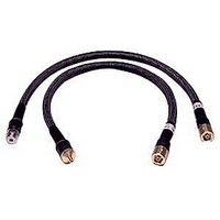
85134F AGILENT TECHNOLOGIES, 85134F Datasheet - Page 13

85134F
Manufacturer Part Number
85134F
Description
Cable Sets
Manufacturer
AGILENT TECHNOLOGIES
Datasheet
1.85134F.pdf
(47 pages)
Specifications of 85134F
Kit Contents
2 Cables
Peak Reflow Compatible (260 C)
No
Cable Length
24.75"
Leaded Process Compatible
No
Connector Type B
3.5mm Female
Connector Type A
2.4mm Female
Lead Length
62.9cm
Lead Free Status / RoHS Status
Contains lead / RoHS non-compliant
Supplemental Characteristics
Table 2-3
are intended to provide additional information useful to your application. Supplemental
characteristics are typical (but not warranted) performance parameters.
Table 2-3 Supplemental Characteristics (1 of 3)
Table 2-3 Supplemental Characteristics (2 of 3)
Center Conductor Pin Depth
Center conductor pin depth is the distance the center conductor mating plane differs from
being flush with the outer conductor mating plane. See
center conductor can be in one of two states: either protruding or recessed.
Protrusion is the condition in which the center conductor extends beyond the outer
conductor mating plane. This condition will indicate a positive value on the connector gage.
Recession is the condition in which the center conductor is set back from the outer
conductor mating plane. This condition will indicate a negative value on the connector
85134E/F/H & 85135E/F
Cable
85134/5E
85134/5F
85134H
Cable Set
85134E
85134F
85134H
85135E
85135F
a. (f) = frequency in GHz.
b. With a 90°, 2.5-inch bend radius.
lists supplemental performance characteristics. These are not specifications, but
Cable Length
cm
97.2
62.9
Number
of Cables
1
2
1
1
2
in
38.25
24.75
Test Set End Connector Type
NMD-2.4 mm -f- Slotted
NMD-2.4 mm -f- Slotted
NMD-2.4 mm -f- Slotted
NMD-2.4 mm -f- Slotted
NMD-2.4 mm -f- Slotted
Approximate
Electrical Length
m
1.150
0.737
45.276
29.016
in
Magnitude and
Phase Stability
<0.22 dB Change
<0.16° (f) + 0.8°
<0.12 dB Change
<0.13° (f) + 0.5°
DUT End Connector Type
PSC-3.5 mm -f- Slotless
NMD-3.5 mm -m- and
PSC-3.5 mm -f- Slotless
NMD-3.5 mm -m-
7 mm
7 mm and 7 mm
Figure 2-1
a,b
Minimum
Recommended
Bend Radius
cm
7.62
The pin depth of a
Supplemental Characteristics
in
3
Specifications
2-3


