85134F AGILENT TECHNOLOGIES, 85134F Datasheet - Page 27
85134F
Manufacturer Part Number
85134F
Description
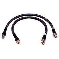
Cable Sets
Manufacturer
AGILENT TECHNOLOGIES
Datasheet
1.85134F.pdf
(47 pages)
Specifications of 85134F
Kit Contents
2 Cables
Peak Reflow Compatible (260 C)
No
Cable Length
24.75"
Leaded Process Compatible
No
Connector Type B
3.5mm Female
Connector Type A
2.4mm Female
Lead Length
62.9cm
Lead Free Status / RoHS Status
Contains lead / RoHS non-compliant


Making Connections
Good connections require a skilled operator. The most common cause of measurement error
is bad connections. The following procedures illustrate how to make good connections.
How to Make a Connection
Preliminary Connection
1. Ground yourself and all devices. Wear a grounded wrist strap and work on a grounded,
2. Visually inspect the connectors. Refer to
3. If necessary, clean the connectors. Refer to
4. Use a connector gage to verify that all center conductors are within the observed pin
2.4 mm and 3.5 mm Connectors:
5. Carefully align the connectors. The male connector center pin must slip concentrically
6. Push the connectors straight together and tighten the connector nut finger-tight.
CAUTION
7. The preliminary connection is tight enough when the mating plane surfaces make
8. Make sure the connectors are properly supported. Relieve any side pressure on the
7 mm Connectors:
5. Fully extend the connector sleeve on one of the connectors. Spin its knurled connector
6. Carefully align the connectors. As you make the actual connection, be sure the
85134E/F/H & 85135E/F
conductive table mat. Refer to
precautions.
depth values in Table 2-3 on page 2-4. Refer to
into the contact finger of the female connector.
Do not twist or screw the connectors together. As the center conductors mate, there is
usually a slight resistance.
uniform, light contact. Do not overtighten this connection.
A connection in which the outer conductors make gentle contact at all points on both
mating surfaces is sufficient. Very light finger pressure is enough to accomplish this.
connection from long or heavy devices or cables.
nut to make sure the threads are fully extended. Fully retract the sleeve on the other
connector. The extended sleeve creates a cylinder into which the other connector fits.
If one of the connectors is fixed (such as on a test port), fully extend that connector
sleeve and fully retract the sleeve on the moveable connector.
connectors align perfectly.
Do not turn the device body. Only turn the connector nut. Damage to the
center conductor can occur if the device body is twisted.
“Electrostatic Discharge” on page 3-2
“Visual Inspection” on page
“Cleaning Connectors” on page
“Gaging Connectors” on page
Use, Maintenance, and Care of the Cables
for ESD
3-3.
Making Connections
3-5.
3-7.
3-13