MRF6V2300NR1 Freescale Semiconductor, MRF6V2300NR1 Datasheet - Page 18
MRF6V2300NR1
Manufacturer Part Number
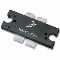
MRF6V2300NR1
Description
MOSFET RF N-CH TO-270-4
Manufacturer
Freescale Semiconductor
Datasheet
1.MRF6V2300NBR5.pdf
(19 pages)
Specifications of MRF6V2300NR1
Transistor Type
N-Channel
Frequency
220MHz
Gain
25.5dB
Voltage - Rated
110V
Current Rating
2.5mA
Current - Test
900mA
Voltage - Test
50V
Power - Output
300W
Package / Case
TO-270-4
Channel Type
N
Channel Mode
Enhancement
Drain Source Voltage (max)
110V
Output Power (max)
300W
Power Gain (typ)@vds
31.4dB
Frequency (min)
10MHz
Frequency (max)
600MHz
Package Type
TO-270 WB EP
Pin Count
5
Input Capacitance (typ)@vds
268@50VpF
Output Capacitance (typ)@vds
120@50VpF
Reverse Capacitance (typ)
2.88@50VpF
Operating Temp Range
-65C to 225C
Drain Efficiency (typ)
61.5%
Mounting
Surface Mount
Mode Of Operation
CW
Number Of Elements
1
Vswr (max)
10
Screening Level
Military
Lead Free Status / RoHS Status
Contains lead / RoHS non-compliant
Noise Figure
-
Lead Free Status / Rohs Status
Compliant
Available stocks
Company
Part Number
Manufacturer
Quantity
Price

Part Number:
MRF6V2300NR1
Manufacturer:
FREESCALE
Quantity:
20 000


18
Application Notes
• AN1907: Solder Reflow Attach Method for High Power RF Devices in Plastic Packages
• AN1955: Thermal Measurement Methodology of RF Power Amplifiers
• AN3263: Bolt Down Mounting Method for High Power RF Transistors and RFICs in Over--Molded Plastic Packages
Engineering Bulletins
• EB212: Using Data Sheet Impedances for RF LDMOS Devices
Software
• Electromigration MTTF Calculator
• RF High Power Model
For Software, do a Part Number search at http://www.freescale.com, and select the “Part Number” link. Go to the Software &
Tools tab on the part’s Product Summary page to download the respective tool.
MRF6V2300NR1 MRF6V2300NBR1
Revision
Refer to the following documents to aid your design process.
The following table summarizes revisions to this document.
0
1
2
3
4
5
Feb. 2007
Feb. 2007
Dec. 2008
May 2007
Jan. 2008
Apr. 2010
Date
• Initial Release of Data Sheet
• Added Fig. 1, Pin Connections, p. 1
• Removed footnote references listed for Operating Junction Temperature, Table 1, Maximum Ratings, p. 1
• Added Max value to Power Gain, Table 5, Functional Tests, p. 2
• Corrected Test Circuit Component part numbers in Table 6, Component Designations and Values for C4,
• Increased operating frequency to 600 MHz, p. 1
• Added Case Operating Temperature limit to the Maximum Ratings table and set limit to 150°C, p. 1
• Corrected C
• Updated PCB information to show more specific material details, Fig. 2, Test Circuit Schematic, p. 3
• Replaced Case Outline 1486--03, Issue C, with 1486--03, Issue D, p. 9--11. Added pin numbers 1 through 4
• Replaced Case Outline 1484--04, Issue D, with 1484--04, Issue E, p. 12--14. Added pin numbers 1 through
• Added Typical Performances table for 27 MHz, 450 MHz applications, p. 2
• Added Figs. 16 and 17, Test Circuit Component Layout -- 27 MHz and 450 MHz, and Tables 7 and 8, Test
• Added Fig. 18, Series Equivalent Source and Load Impedance for 27 MHz, 450 MHz, p. 11
• Operating Junction Temperature increased from 200°C to 225°C in Maximum Ratings table, related
• Added Electromigration MTTF Calculator and RF High Power Model availability to Product Software,
C19, C5, C18, C9, C12, C14, and C23, p. 3
Dynamic Characteristics table, p. 2
on Sheet 1.
4 on Sheet 1, replacing Gate and Drain notations with Pin 1 and Pin 2 designations.
Circuit Component Designations and Values -- 27 MHz and 450 MHz, p. 9, 10
“Continuous use at maximum temperature will affect MTTF” footnote added and changed 200°C to 225°C
in Capable Plastic Package bullet, p. 1
p. 18
PRODUCT DOCUMENTATION AND SOFTWARE
iss
test condition to indicate AC stimulus on the V
REVISION HISTORY
Description
GS
connection versus the V
Freescale Semiconductor
DS
RF Device Data
connection,
Related parts for MRF6V2300NR1
Image
Part Number
Description
Manufacturer
Datasheet
Request
R

Part Number:
Description:
Manufacturer:
Freescale Semiconductor, Inc
Datasheet:
Part Number:
Description:
Manufacturer:
Freescale Semiconductor, Inc
Datasheet:
Part Number:
Description:
Manufacturer:
Freescale Semiconductor, Inc
Datasheet:
Part Number:
Description:
Manufacturer:
Freescale Semiconductor, Inc
Datasheet:
Part Number:
Description:
Manufacturer:
Freescale Semiconductor, Inc
Datasheet:
Part Number:
Description:
Manufacturer:
Freescale Semiconductor, Inc
Datasheet:
Part Number:
Description:
Manufacturer:
Freescale Semiconductor, Inc
Datasheet:
Part Number:
Description:
Manufacturer:
Freescale Semiconductor, Inc
Datasheet:
Part Number:
Description:
Manufacturer:
Freescale Semiconductor, Inc
Datasheet:
Part Number:
Description:
Manufacturer:
Freescale Semiconductor, Inc
Datasheet:
Part Number:
Description:
Manufacturer:
Freescale Semiconductor, Inc
Datasheet:
Part Number:
Description:
Manufacturer:
Freescale Semiconductor, Inc
Datasheet:
Part Number:
Description:
Manufacturer:
Freescale Semiconductor, Inc
Datasheet:
Part Number:
Description:
Manufacturer:
Freescale Semiconductor, Inc
Datasheet:
Part Number:
Description:
Manufacturer:
Freescale Semiconductor, Inc
Datasheet: