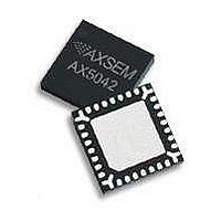
AX5042-QFN28-TU AXSEM, AX5042-QFN28-TU Datasheet - Page 24

AX5042-QFN28-TU
Manufacturer Part Number
AX5042-QFN28-TU
Description
RF Transceiver Narrow-Band-IC
Manufacturer
AXSEM
Datasheet
1.AX5042-QFN28-TU.pdf
(45 pages)
Specifications of AX5042-QFN28-TU
Number Of Receivers
1
Number Of Transmitters
1
Wireless Frequency
433 MHz, 868 MHz, 915 MHz
Interface Type
SPI, UART
Output Power
14.5 dBm
Operating Supply Voltage
2.3 V to 2.8 V
Maximum Operating Temperature
+ 85 C
Maximum Supply Current
54 mA
Minimum Operating Temperature
- 40 C
Modulation
ASK, FSK, PSK
Lead Free Status / RoHS Status
Lead free / RoHS Compliant
24
Circuit Description
5.8.
The mixer is followed by a complex band-pass IF filter, which suppresses the down-mixed
image while the wanted signal is amplified. The centre frequency of the filter is 1 MHz, with a
passband width of 1 MHz. The RF frequency generation subsystem must be programmed in
such a way that for all possible modulation schemes the IF frequency spectrum fits into the
passband of the analog filter.
5.9.
The digital IF channel filter and the demodulator extract the data bit-stream from the
incoming IF signal. They must be programmed to match the modulation scheme as well as
the bit rate. Inaccurate programming will lead to loss of sensitivity.
The channel filter offers bandwidths of 4.8 kHz up to 600 kHz. Data-rates down to 1.2 kbit/s
can be demodulated, but sensitivities will not increase significantly vs. 4.8 kbit/s.
For detailed instructions how to program the digital channel filter and the demodulator see
the
following table. The register setups typically must be done once at power-up of the device.
Registers
Register
CICDECHI, CICDECLO
DATARATEHI, DATARATELO
TMGGAINHI, TMGGAINLO
MODULATION
PHASEGAIN, FREQGAIN,
FREQGAIN2, AMPLGAIN
AGCATTACK, AGCDECAY
TXRATE
FSKDEV
Version 2.4
AX5042
Analog IF Filter
Digital IF Channel Filter and Demodulator
Programming Manual, an overview of the registers involved is given in the
Remarks
This register programs the bandwidth of the digital channel filter.
These registers specify the receiver bit rate, relative to the channel filter
bandwidth.
These registers specify the aggressiveness of the receiver bit timing recovery.
More aggressive settings allow the receiver to synchronize with shorter
preambles, at the expense of more timing jitter and thus a higher bit error rate
at a given signal-to-noise ratio.
This register selects the modulation to be used by the transmitter and the
receiver, i.e. whether ASK, PSK , FSK, MSK, GFSK, GMSK or OQPSK should be
used.
These registers control the bandwidth of the phase, frequency offset and
amplitude tracking loops. Recommended settings are provided in the
Programming Manual.
These registers control the AGC (automatic gain control) loop slopes, and thus
the speed of gain adjustments. The faster the bit rate, the faster the AGC loop
should be. Recommended settings are provided in the Programming Manual.
These registers control the bit rate of the transmitter.
These registers control the frequency deviation of the transmitter in FSK mode.
The receiver does not explicitly need to know the frequency deviation, only the
channel filter bandwidth has to be set wide enough for the complete
modulation to pass.
Datasheet AX5042


