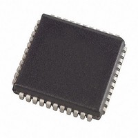
SST89E58RD2-40-I-NJE Microchip Technology, SST89E58RD2-40-I-NJE Datasheet - Page 51

SST89E58RD2-40-I-NJE
Manufacturer Part Number
SST89E58RD2-40-I-NJE
Description
4.5 To 5.5V FlashFlex 8-bit 8051 Microcontroller 44 PLCC TUBE
Manufacturer
Microchip Technology
Series
FlashFlex®r
Specifications of SST89E58RD2-40-I-NJE
Core Processor
8051
Core Size
8-Bit
Speed
40MHz
Connectivity
EBI/EMI, SPI, UART/USART
Peripherals
Brown-out Detect/Reset, POR, WDT
Number Of I /o
36
Program Memory Size
32KB (32K x 8)
Program Memory Type
FLASH
Eeprom Size
8K x 8
Ram Size
1K x 8
Voltage - Supply (vcc/vdd)
4.5 V ~ 5.5 V
Oscillator Type
External
Operating Temperature
-40°C ~ 85°C
Package / Case
44-LCC (J-Lead)
Processor Series
FlashFlex51
Core
C51
Data Bus Width
8 bit
Data Ram Size
1 KB
Interface Type
SPI
Maximum Clock Frequency
40 MHz
Number Of Programmable I/os
5
Number Of Timers
3
Operating Supply Voltage
4.5 V to 5.5 V
Maximum Operating Temperature
+ 85 C
Mounting Style
SMD/SMT
Minimum Operating Temperature
- 40 C
Lead Free Status / RoHS Status
Lead free / RoHS Compliant
Data Converters
-
Lead Free Status / Rohs Status
Details
Available stocks
Company
Part Number
Manufacturer
Quantity
Price
Company:
Part Number:
SST89E58RD2-40-I-NJE
Manufacturer:
Microchip Technology
Quantity:
10 000
Part Number:
SST89E58RD2-40-I-NJE
Manufacturer:
SST
Quantity:
20 000
FlashFlex MCU
SST89E54RD2A/RDA / SST89E58RD2A/RDA
TABLE
TABLE
©2008 Silicon Storage Technology, Inc.
Without Interrupt enabled
With Interrupt enabled
-
-
-
-
-
-
-
-
-
-
-
-
-
-
-
-
-
1
1
1. User should not write ‘1’s to reserved bits. The value read from a reserved bit is indeterminate.
2. y = 0, 1, 2, 3, 4
3. A 0 disables toggle function. A 1 enables toggle function on CEX[4:0] pin.
4. For PCA WDT mode, also set the WDTE bit in the CMOD register to enable the reset output signal.
1. User should not write ‘1’s to reserved bits. The value read from a reserved bit is indeterminate.
2. y = 0, 1, 2, 3, 4
3. No PCA interrupt is needed to generate the PWM.
4. A 0 disables toggle function. A 1 enables toggle function on CEX[4:0] pin.
5. Enabling an interrupt for the Watchdog Timer would defeat the purpose of the Watchdog Timer.
6. For PCA WDT mode, also set the WDTE bit in the CMOD register to enable the reset output signal.
ECOMy
ECOMy
0
0
0
0
1
1
1
1
0
0
0
1
1
1
1
8-5: PCA Module Modes
8-6: PCA Module Modes
2
2
CAPPy
CAPPy
0
1
0
1
0
0
0
0
1
0
1
0
0
0
0
2
2
CAPNy
CAPNy
0
0
1
1
0
0
0
0
0
1
1
0
0
0
0
2
2
MATy
MATy
0
0
0
0
1
1
0
1
0
0
0
1
1
0
1
2
2
TOGy
0 or 1
TOGy
0 or 1
0
0
0
0
0
1
0
0
0
0
0
1
0
3
2
4
2
PWMy
PWMy
0
0
0
0
0
0
1
0
0
0
0
0
0
1
0
51
2
2
ECCFy
ECCFy
X
X
0
0
0
0
0
0
0
0
1
1
1
1
1
3
5
2
2
Module Code
No Operation
16-bit capture on positive-edge trigger at CEX[4:0]
16-bit capture on negative-edge trigger at
CEX[4:0]
16-bit capture on positive/negative-edge
trigger at CEX[4:0]
Compare: software timer
Compare: high-speed output
Compare: 8-bit PWM
Compare: PCA WDT (CCAPM4 only)
Module Code
16-bit capture on positive-edge trigger at CEX[4:0]
16-bit capture on negative-edge trigger at CEX[4:0]
16-bit capture on positive/negative-edge
trigger at CEX[4:0]
Compare: software timer
Compare: high-speed output
Compare: 8-bit PWM
Compare: PCA WDT (CCAPM4 only)
S71339-02-000
4
6
Data Sheet
T8-5.0 1339
T8-6.0 1339
02/08


