SST89E58RD2-40-I-NJE Microchip Technology, SST89E58RD2-40-I-NJE Datasheet - Page 56
SST89E58RD2-40-I-NJE
Manufacturer Part Number
SST89E58RD2-40-I-NJE
Description
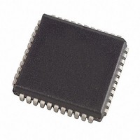
4.5 To 5.5V FlashFlex 8-bit 8051 Microcontroller 44 PLCC TUBE
Manufacturer
Microchip Technology
Series
FlashFlex®r
Specifications of SST89E58RD2-40-I-NJE
Core Processor
8051
Core Size
8-Bit
Speed
40MHz
Connectivity
EBI/EMI, SPI, UART/USART
Peripherals
Brown-out Detect/Reset, POR, WDT
Number Of I /o
36
Program Memory Size
32KB (32K x 8)
Program Memory Type
FLASH
Eeprom Size
8K x 8
Ram Size
1K x 8
Voltage - Supply (vcc/vdd)
4.5 V ~ 5.5 V
Oscillator Type
External
Operating Temperature
-40°C ~ 85°C
Package / Case
44-LCC (J-Lead)
Processor Series
FlashFlex51
Core
C51
Data Bus Width
8 bit
Data Ram Size
1 KB
Interface Type
SPI
Maximum Clock Frequency
40 MHz
Number Of Programmable I/os
5
Number Of Timers
3
Operating Supply Voltage
4.5 V to 5.5 V
Maximum Operating Temperature
+ 85 C
Mounting Style
SMD/SMT
Minimum Operating Temperature
- 40 C
Lead Free Status / RoHS Status
Lead free / RoHS Compliant
Data Converters
-
Lead Free Status / Rohs Status
Details
Available stocks
Company
Part Number
Manufacturer
Quantity
Price
Company:

Part Number:
SST89E58RD2-40-I-NJE
Manufacturer:
Microchip Technology
Quantity:
10 000
Part Number:
SST89E58RD2-40-I-NJE
Manufacturer:
SST
Quantity:
20 000


Data Sheet
8.3.5 Watchdog Timer
The Watchdog Timer mode is used to improve reliability in
the system without increasing chip count (See Figure 8-6).
Watchdog Timers are useful for systems that are suscepti-
ble to noise, power glitches, or electrostatic discharge. It
can also be used to prevent a software deadlock. If during
the execution of the user’s code, there is a deadlock, the
Watchdog Timer will time out and an internal reset will
occur. Only module 4 can be programmed as a Watchdog
Timer (but still can be programmed to other modes if the
Watchdog Timer is not used).
To use the Watchdog Timer, the user pre-loads a 16-bit
value in the compare register. Just like the other compare
modes, this 16-bit value is compared to the PCA timer
value. If a match is allowed to occur, an internal reset will be
generated. This will not cause the RST pin to be driven high.
In order to hold off the reset, the user has three options:
The first two options are more reliable because the Watch-
dog Timer is never disabled as in option #3. If the program
counter ever goes astray, a match will eventually occur and
cause an internal reset. The second option is also not rec-
ommended if other PCA modules are being used. Remem-
ber, the PCA timer is the time base for all modules;
changing the time base for other modules would not be a
good idea. Thus, in most application the first solution is the
best option.
©2008 Silicon Storage Technology, Inc.
1. periodically change the compare value so it will
2. periodically change the PCA timer value so it will
3. disable the watchdog timer by clearing the WDTE
never match the PCA timer,
never match the compare values, or
bit before a match occurs and then re-enable it.
SST89E54RD2A/RDA / SST89E58RD2A/RDA
56
Use the code below to initialize the Watchdog Timer. Mod-
ule 4 can be configured in either compare mode, and the
WDTE bit in CMOD must also be set. The user’s software
then must periodically change (CCAP4H, CCAP4L) to
keep a match from occurring with the PCA timer (CH, CL).
This code is given in the Watchdog routine below.
This routine should not be part of an interrupt service rou-
tine. If the program counter goes astray and gets stuck in an
infinite loop, interrupts will still be serviced and the watchdog
will keep getting reset. Thus, the purpose of the watchdog
would be defeated. Instead, call this subroutine from the
main program of the PCA timer.
;==============================================
Init_Watchdog:
;==============================================
;Main program goes here, but call WATCHDOG periodically.
;==============================================
WATCHDOG:
;==============================================
MOVCCAPM4, #4CH; Module 4 in compare mode
MOVCCAP4L, #0FFH; Write to low byte first
MOVCCAP4H, #0FFH; Before PCA timer counts up
ORLCMOD, #40H; Set the WDTE bit to enable the
CLR EA; Hold off interrupts
MOVCCAP4L, #00; Next compare value is within
MOVCCAP4H, CH; 65,535 counts of the
SETBEA; timer value
RET
; to FFFF Hex, these compare
; values must be changed.
; watchdog timer without
; changing the other bits in
; CMOD
; current PCA
FlashFlex MCU
S71339-02-000
02/08
Related parts for SST89E58RD2-40-I-NJE
Image
Part Number
Description
Manufacturer
Datasheet
Request
R

Part Number:
Description:
4.5 To 5.5V FlashFlex 8-bit 8051 Microcontroller 44 TQFP 10x10x1mm TRAY
Manufacturer:
Microchip Technology
Datasheet:

Part Number:
Description:
4.5 To 5.5V FlashFlex 8-bit 8051 Microcontroller 44 PLCC TUBE
Manufacturer:
Microchip Technology
Datasheet:
Part Number:
Description:
4.5 To 5.5V FlashFlex 8-bit 8051 Microcontroller 44 TQFP 10x10x1mm TRAY
Manufacturer:
Microchip Technology
Datasheet:

Part Number:
Description:
Manufacturer:
Microchip Technology Inc.
Datasheet:
Part Number:
Description:
Manufacturer:
Microchip Technology Inc.
Datasheet:
Part Number:
Description:
Manufacturer:
Microchip Technology Inc.
Datasheet:
Part Number:
Description:
Manufacturer:
Microchip Technology Inc.
Datasheet:
Part Number:
Description:
Manufacturer:
Microchip Technology Inc.
Datasheet:
Part Number:
Description:
Manufacturer:
Microchip Technology Inc.
Datasheet:
Part Number:
Description:
Manufacturer:
Microchip Technology Inc.
Datasheet: