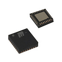
KSZ8851SNLI Micrel Inc, KSZ8851SNLI Datasheet - Page 60

KSZ8851SNLI
Manufacturer Part Number
KSZ8851SNLI
Description
Manufacturer
Micrel Inc
Datasheet
1.KSZ8851SNLI.pdf
(80 pages)
Specifications of KSZ8851SNLI
Operating Supply Voltage (typ)
3.3V
Operating Temperature Classification
Industrial
Mounting
Surface Mount
Pin Count
32
Lead Free Status / RoHS Status
Supplier Unconfirmed
Available stocks
Company
Part Number
Manufacturer
Quantity
Price
Part Number:
KSZ8851SNLI
Manufacturer:
MICROCHIP/微芯
Quantity:
20 000
Company:
Part Number:
KSZ8851SNLI TR
Manufacturer:
Kendin
Quantity:
700
Company:
Part Number:
KSZ8851SNLI TR
Manufacturer:
Micrel
Quantity:
250
Company:
Part Number:
KSZ8851SNLI-TR
Manufacturer:
MXIC
Quantity:
15 000
Company:
Part Number:
KSZ8851SNLITR
Manufacturer:
MICREL
Quantity:
3 500
Part Number:
KSZ8851SNLITR
Manufacturer:
MICREL/麦瑞
Quantity:
20 000
0xCA – 0xCF: Reserved
Indirect Access Data Low Register (0xD0 – 0xD1): IADLR
This register contains the indirect data (low word) for MIB counter.
Indirect Access Data High Register (0xD2 – 0xD3): IADHR
This register contains the indirect data (high word) for MIB counter.
Power Management Event Control Register (0xD4 – 0xD5): PMECR
This register is used to control the KSZ8851SNL power management event, capabilities and status.
August 2009
Micrel, Inc.
Bit
15-13
12
11-10
9-5
4-0
Bit
15-0
Bit
15-0
Bit
15
14
13
12
11-8
Default Value
-
0
0
0
0x0
0x0
-
Default
0x0
0x0
0x00
Default
0x0000
Default
0x0000
R/W
RW
RW
RW
RW
RW
R/W
RW
R/W
RW
R/W
RO
RW
RW
RW
RW
Description
Reserved.
Read Enable
1 = Read cycle is enabled (MIB counter will clear after read).
0 = No operation.
Table Select
00 = reserved.
01 = reserved.
10 = reserved.
11 = MIB counter selected.
Reserved
Indirect Address
Bit 4-0 of indirect address for 32 MIB counter locations.
Description
Indirect Low Word Data
Bit 15-0 of indirect data.
Description
Indirect High Word Data
Bit 31-16 of indirect data.
Description
Reserved
PME Delay Enable
This bit is used to enable the delay of PME output pin 2 assertion.
When this bit is set to 1, the device will not assert the PME output till the device’s all
clocks are running and ready for host access.
When this bit is set to 0, the device will assert the PME output without delay.
This bit is only valid when Auto Wake-Up Enable (bit7) is set to 1 in this register.
Reserved
PME Output Polarity
This bit is used to control the PME output pin 2 polarity.
When this bit is set to 1, the PME output pin 2 is active high.
When this bit is set to 0, the PME output pin 2 is active low.
Wake-on-LAN to PME Output Enable
These four bits are used to enable the PME output pin 2 asserted when one of these
wake-on-LAN events is detected:
Bit 11: is corresponding to receive wake-up frame.
Bit 10: is corresponding to receive magic packet.
Bit 9: is corresponding to link change from down to up.
60
KSZ8851SNL/SNLI
M9999-083109-2.0


