PAXLSG00 Red Lion Controls, PAXLSG00 Datasheet - Page 3
PAXLSG00
Manufacturer Part Number
PAXLSG00
Description
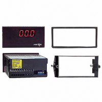
METER STRAIN GAGE 3 1/2-DIGIT
Manufacturer
Red Lion Controls
Series
PAX®LITEr
Type
Strain Gage, Millivolt Meterr
Datasheet
1.PAXLSG00.pdf
(8 pages)
Specifications of PAXLSG00
Measuring Range
±2V
Display Style
Red Characters, Black Background
Display Type
LED
Display Face Size
3.80" L x 1.95" W (96.5 x 49.5mm)
Display Digits
3.5
Display Digits - Height
0.560" (14.22mm)
Mounting Type
Panel Mount
Termination
Terminal Block
Voltage - Supply
85 ~ 250VAC
No. Of Digits / Alpha
3-1/2
Meter Range
0mV To 10mV / 0V To 2V
Digit Height
14.2mm
Power Consumption
6VA
Operating Temperature Range
0°C To +60°C
Supply Voltage Ac, Min
85V
Signal Input Type
Strain Gage
Character Size
0.56"
Display Font Color
Red
Rohs Compliant
NA
Lead Free Status / RoHS Status
Contains lead / RoHS non-compliant
Other names
RLC114


UNITS LABEL KIT (PAXLBK)
using the Units Label Kit. The backlight is controlled by a DIP switch.
1.
2. OVER-RANGE INDICATION: Indicated by blanking 3 least significant
3. POWER:
4. INPUT SIGNAL: Single-ended or differential input, ±2.0 V max. Gain
5. INPUT IMPEDANCE: 100 MΩ
6. LINEARITY: ±(0.05% ±1 digit)
7. LOW FREQUENCY NOISE REJECTION:
8. RESPONSE TIME: 2.0 seconds to settle from step input.
9. READING RATE: 2.5 updated readings/second, nominal.
10. EXCITATION SUPPLY:
11. ENVIRONMENTAL CONDITIONS:
12. CERTIFICATIONS AND COMPLIANCES:
G
A
DISPLAY: 3 1/2-digit, 0.56" (14.2 mm) high, 7-segment LED, (-) minus sign
Each meter has a units indicator with backlighting that can be customized
displayed when voltage is negative. Decimal points inserted before 1st, 2nd,
or 3rd least significant digits by DIP switch selection.
digits.
AC Power: 85 to 250 VAC, 50/60 HZ, 6 VA
Isolation: 2300 Vrms for 1 min. to all inputs.
(Sensitivity) is adjustable from 200 Units of Numerical Readout/millivolt input
(gives full scale readout of 1999 at 10 mV input), to less than 1 Unit of
Numerical Readout/mV (gives full scale readout of 1999 at 2.0 V input).
Maximum common mode voltage swing with respect to signal ground, 0 to 7 V.
Note: Absolute maximum voltage that can be applied between the two input
Normal Mode Rejection: 84 dB @ 50/60 Hz
Common Mode Rejection: 50 dB with respect to excitation common;
Jumper Selectable: 5 VDC @ 60 mA max., ±2%
Temperature coefficient (ratio metric): 20 ppm/°C max.
Operating Temperature: 0° to 60°C
Storage Temperature: -40° to 80°C
Operating and Storage Humidity: 85% max. relative humidity (non-
Span Temperature Coeff.: 100 PPM/°C
Offset Temperature Coeff.: 100 PPM/°C
Altitude: Up to 2000 meters
SAFETY
UL Recognized Component, File # E179259, UL61010A-1, CSA C22.2 No. 61010-1
UL Listed, File # E137808, UL508, CSA C22.2 No. 14-M95
IECEE CB Scheme Test Certificate # UL/8843A/UL
terminals or between input and signal common is 50 VDC.
110 dB with respect to earth ground.
condensing)
Recognized to U.S. and Canadian requirements under the Component
Recognition Program of Underwriters Laboratories, Inc.
LISTED by Und. Lab. Inc. to U.S. and Canadian safety standards
Type 4X Enclosure rating (Face only), UL50
CB Scheme Test Report # 04ME11209-20041018
IEC 61010-1, EN 61010-1: Safety requirements for electrical equipment
IP65 Enclosure rating (Face only), IEC 529
IP20 Enclosure rating (Rear of unit), IEC 529
CCESSORIES
ENERAL
Issued by Underwriters Laboratories, Inc.
for measurement, control, and laboratory use, Part 1.
10 VDC @ 120 mA max., ±2%
M
ETER
S
PECIFICATIONS
3
13. CONNECTIONS: High compression cage-clamp terminal block
14. CONSTRUCTION: This unit is rated for NEMA 4X/IP65 outdoor use.
15. WEIGHT: 0.65 lbs (0.24 kg)
ELECTROMAGNETIC COMPATIBILITY
Emissions and Immunity to EN 61326: Electrical Equipment for
Measurement, Control and Laboratory use.
Notes:
Wire Strip Length: 0.3" (7.5 mm)
Wire Gage: 30-14 AWG copper wire
Torque: 4.5 inch-lbs (0.51 N-m) max.
IP20 Touch safe. Installation Category II, Pollution Degree 2. One piece
bezel/case. Flame resistant. Panel gasket and mounting clip included.
Immunity to Industrial Locations:
Electrostatic discharge
Electromagnetic RF fields
Fast transients (burst)
Surge
RF conducted interference
Power frequency magnetic fields EN 61000-4-8
Voltage dip/interruptions
Emissions:
Emissions
1. Criterion A: Normal operation within specified limits.
2. Criterion B: Temporary loss of performance from which the unit self-
recovers.
EN 61000-4-2
EN 61000-4-3
EN 61000-4-4
EN 61000-4-5
EN 61000-4-6
EN 61000-4-11
EN 55011
Criterion A
4 kV contact discharge
8 kV air discharge
Criterion B
10 V/m
Criterion B
2 kV power
2 kV signal
Criterion A
1 kV L-L,
1 kV signal
Criterion A
3 V/rms
Criterion A
30 A/m
Criterion A
0.5 cycle
Class B
2 kV L&N-E power