PAXLSG00 Red Lion Controls, PAXLSG00 Datasheet - Page 5
PAXLSG00
Manufacturer Part Number
PAXLSG00
Description
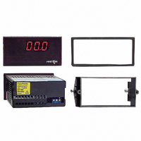
METER STRAIN GAGE 3 1/2-DIGIT
Manufacturer
Red Lion Controls
Series
PAX®LITEr
Type
Strain Gage, Millivolt Meterr
Datasheet
1.PAXLSG00.pdf
(8 pages)
Specifications of PAXLSG00
Measuring Range
±2V
Display Style
Red Characters, Black Background
Display Type
LED
Display Face Size
3.80" L x 1.95" W (96.5 x 49.5mm)
Display Digits
3.5
Display Digits - Height
0.560" (14.22mm)
Mounting Type
Panel Mount
Termination
Terminal Block
Voltage - Supply
85 ~ 250VAC
No. Of Digits / Alpha
3-1/2
Meter Range
0mV To 10mV / 0V To 2V
Digit Height
14.2mm
Power Consumption
6VA
Operating Temperature Range
0°C To +60°C
Supply Voltage Ac, Min
85V
Signal Input Type
Strain Gage
Character Size
0.56"
Display Font Color
Red
Rohs Compliant
NA
Lead Free Status / RoHS Status
Contains lead / RoHS non-compliant
Other names
RLC114


DEADLOAD COMPENSATION
range of the input. To use this range, the output of the bridge can be offset a
small amount by applying a fixed resistor across one arm of the bridge. This
shifts the electrical output of the bridge downward to within the operating range
of the meter. A 100 K ohm fixed resistor shifts the bridge output approximately
-10 mV (350 ohm bridge, 10 V excitation).
low temperature coefficient of resistance.
WIRING OVERVIEW
back of the meter. All conductors should conform to the meter’s voltage and
current ratings. All cabling should conform to appropriate standards of good
installation, local codes and regulations. It is recommended that power supplied
to the meter (AC) be protected by a fuse or circuit breaker.
meter case against those shown in wiring drawings for proper wire position. Strip
the wire, leaving approximately 0.3" (7.5 mm) bare lead exposed (stranded wires
should be tinned with solder). Insert the lead under the correct screw-clamp
terminal and tighten until the wire is secure. (Pull wire to verify tightness.)
EMC INSTALLATION GUIDELINES
Magnetic Interference (EMI), proper installation and wiring methods must be
followed to ensure compatibility in each application. The type of the electrical
noise, its source or the method of coupling into the unit may be different for
various installations. Listed below are some EMC guidelines for successful
installation in an industrial environment.
1. The meter should be mounted in a metal enclosure, which is properly
2. Never run Signal or Control cables in the same conduit or raceway with AC
3.1 POWER WIRING
AC Power
Terminal 1: VAC
Terminal 2: VAC
3.2 INPUT SIGNAL WIRING
3.0 W
2-Wire Single Ended Input
In some cases, the combined deadload and liveload output may exceed the
Connect the resistor between +SIG and -SIG. Use a metal film resistor with a
Electrical connections are made via screw-clamp terminals located on the
When wiring the meter, compare the numbers embossed on the back of the
Although this meter is designed with a high degree of immunity to Electro-
connected to protective earth.
power lines, conductors feeding motors, solenoids, SCR controls, and
heaters, etc. The cables should be run in metal conduit that is properly
grounded. This is especially useful in applications where cable runs are long
IRING THE
4-Wire Bridge Input
M
Excitation Power
Terminal 3: Common
Terminal 4: Excitation +
ETER
5
3. Signal or Control cables within an enclosure should be routed as far away as
4. In extremely high EMI environments, the use of external EMI suppression
5. Long cable runs are more susceptible to EMI pickup than short cable runs.
6. Switching of inductive loads produces high EMI. Use of snubbers across
BRIDGE COMPLETION RESISTORS
employed externally to the meter. Only use metal film resistors with a low
temperature coefficient of resistance.
resistance bridges and do not require bridge completion resistors.
and portable two-way radios are used in close proximity or if the installation
is near a commercial radio transmitter.
possible from contactors, control relays, transformers, and other noisy
components.
devices, such as ferrite suppression cores, is effective. Install them on Signal
and Control cables as close to the unit as possible. Loop the cable through the
core several times or use multiple cores on each cable for additional protection.
Install line filters on the power input cable to the unit to suppress power line
interference. Install them near the power entry point of the enclosure. The
following EMI suppression devices (or equivalent) are recommended:
Therefore, keep cable runs as short as possible.
inductive loads suppresses EMI.
For single strain gage applications, bridge completion resistors must be
Load cells and pressure transducers are normally implemented as full
Ferrite Suppression Cores for signal and control cables:
Line Filters for input power cables:
Note: Reference manufacturer’s instructions when installing a line filter.
Snubber: RLC#SNUB0000.
Fair-Rite # 0443167251 (RLC #FCOR0000)
TDK # ZCAT3035-1330A
Steward #28B2029-0A0
Schaffner # FN610-1/07 (RLC #LFIL0000)
Schaffner # FN670-1.8/07
Corcom #1VR3
6-Wire Bridge Input