PAXLSG00 Red Lion Controls, PAXLSG00 Datasheet - Page 7
PAXLSG00
Manufacturer Part Number
PAXLSG00
Description
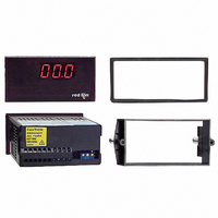
METER STRAIN GAGE 3 1/2-DIGIT
Manufacturer
Red Lion Controls
Series
PAX®LITEr
Type
Strain Gage, Millivolt Meterr
Datasheet
1.PAXLSG00.pdf
(8 pages)
Specifications of PAXLSG00
Measuring Range
±2V
Display Style
Red Characters, Black Background
Display Type
LED
Display Face Size
3.80" L x 1.95" W (96.5 x 49.5mm)
Display Digits
3.5
Display Digits - Height
0.560" (14.22mm)
Mounting Type
Panel Mount
Termination
Terminal Block
Voltage - Supply
85 ~ 250VAC
No. Of Digits / Alpha
3-1/2
Meter Range
0mV To 10mV / 0V To 2V
Digit Height
14.2mm
Power Consumption
6VA
Operating Temperature Range
0°C To +60°C
Supply Voltage Ac, Min
85V
Signal Input Type
Strain Gage
Character Size
0.56"
Display Font Color
Red
Rohs Compliant
NA
Lead Free Status / RoHS Status
Contains lead / RoHS non-compliant
Other names
RLC114


and the method chosen depends largely on the nature of the application. The
three methods are:
VOLTAGE CALIBRATION
measured input voltage that can be varied through the range normally delivered
by the transducer (See Voltage Calibration Circuit, below). The PAXLSG is then
adjusted to provide the proper readout.
SYSTEM CALIBRATION
final installation, or in a bench set-up simulating the actual installation.
Accurately known inputs are then applied to the transducer (i.e. load, pressure,
force, etc.), and the PAXLSG adjustments are made to provide the desired
indication. This method is usually preferable to the Voltage Calibration method
since it calibrates both the transducer and the PAXLSG as a combination, and
reduces the inherent risk of inaccuracy or errors accumulated by separate
calibration. However, it can only be used in applications where the parameter to
be indicated can be easily varied and accurately measured or established. It is
also very awkward to use if an offset or transducer unbalance must be dealt with
because of Offset/Gain adjustment interaction.
COMBINATION VOLTAGE/SYSTEM CALIBRATION
exists and where high accuracy is required in the final indication, it may be
desirable to voltage calibrate the unit first to get it very close to its final settings.
Then, after final installation, the unit can be “tweaked” to its final settings while
using accurately known inputs to the system. These various factors make it
impossible to set up one calibration procedure to cover all applications.
However, using the following information on Voltage Calibration together with
the examples given should provide a good basis for handling virtually any
calibration requirement.
CALIBRATION EXAMPLE
calibration circuit shown below.
VOLTAGE CALIBRATION CIRCUIT
ranges of 0 to ±22 mV, 0 to +44 mV, or 0 to -44 mV, depending on the setting
of R2. The range can be increased or decreased by adjusting the value of R3
(shown as 40 K). An accurate reference millivoltmeter is used to set up the
calibration voltage, and a “Zero Switch” facilitates balancing without
readjusting the calibration voltage. High-stability metalized resistors (1% tol.)
should be used. The use of a dummy bridge insures a common-mode voltage
during calibration that is very similar to that of the actual transducer.
SET-UP
Span (Rs) and the required GAIN must be determined.
WHERE
5.0 C
(Using 350 Ohm Dummy Bridge)
There are three different methods that can be used to calibrate the PAXLSG,
In this method, the transducer signal is simply replaced with an accurately
In this method, the transducer is connected to the input of the PAXLSG in the
In applications where tare-load, offset, or substantial transducer unbalance
“Voltage Calibration” can be easily performed for any application, using the
This 350 Ohms “Dummy Bridge” circuit delivers calibration voltages in
Before starting the procedure, the Input Swing Voltage (Vs), the Readout
Rs = (Max. Numerical Display) - (Min. Numerical Display) Disregard Decimal Points
Vs = (mV in @ Max. Display) - (mV in @ Min. Display)
GAIN = Rs = Units/mV
:
:
Vs
ALIBRATING THE
M
ETER
7
EXAMPLE: Readout is to be 5.00 Units @ 2 mV minimum, and 15.00 Units
CALIBRATION PROCEDURE
1. Set the Coarse Gain Select Switches, S5 through S9 to establish a maximum
2. Connect the unit to the Calibration Circuit as shown. Set the excitation
3. Place unit in the case and turn power on to the unit. Allow 10 minutes of
4. Close the “Zero Switch” of the calibration circuit to obtain zero input voltage.
5. Open the “Zero Switch” of the calibrating circuit and set the input voltage to
6. Repeat Step 4 and readjust zero if required. If zero readjustment was needed,
*7. Set the calibration voltage to the minimum input level (2 mV in this
*8. Place unit in the case and turn power on to the unit. Use the fine offset
@ 18 mV maximum. The transducer is a 350 Ω strain-gage bridge requiring
10 VDC excitation.
Rs = 1500 - 500 = 1000 Units
Vs = 18 mV - 2 mV = 16 mV
GAIN = 1000 = 62.5 Units/mV
readout @ zero input) this example was intentionally chosen because it included
an offset reading at zero input. It will be used in the Calibration Procedure
below to illustrate the most convenient way to handle offset situations without
excessive interaction of gain and offset adjustments. If a zero-based example
had been given, the minimum readout and input voltage would have both been
zero. Rs and Vs would then simply be the maximum values of readout and input
voltage respectively, gain would just be the ratio of (Max. Readout/Max. Input
mV), and Steps 7 and 8 of the procedure below could be eliminated.
range just exceeding the required gain. Referring to the example given, the
required gain was calculated to be 62.5 Units/mV. Setting switches S6 and S7
ON gives 50 + 16 = 66 Units/mV, which is just above the required amount. The
following chart gives an approximate gain adjustment value for each switch:
All offset switches, S2, 3, and 4, should be off.
voltage range jumper to the 10 V position.
warm-up time for stabilization.
Adjust the fine offset control to get a zero readout.
the calculated swing voltage, Vs. (Vs is 16 mV in the example given.) Now,
adjust the Gain Coarse and Fine Controls to get a readout equal to the
Readout Span.
(Rs = 1000 Units in the example given.)
repeat Step 5, then back to Step 4, etc., until Zero and Rs readings are
acceptable.
example). Record the meter reading (125 in this example). Power the meter
down and remove it from the case. Set the Coarse Offset Select Switches to
get the corresponding minimum readout (add the switch offset value(s) to the
recorded meter reading). In the example given, the minimum readout was
500 units @ 2 mV, therefore setting switches 3 and 4 gives us 125 (meter
reading) + 125 (SW4) + 250 (SW3) = 500. The following chart gives an
approximate offset adjustment value for each switch.
adjustment to fine tune the desired minimum reading (500 in this example).
Vary the input from the minimum to maximum levels and check the
corresponding readouts. Fine-tune if necessary by readjusting the fine gain
adjustment at the maximum end and the fine offset adjustment at the
minimum end. (In the example, readout is 500 @ 2 mV min. and 1500 @ 18
mV max.) Alternate between minimum and maximum inputs as required
until readout is within desired tolerance at the extremes.9. Set appropriate
decimal point switch (S2 for the example given).
The unit is now ready for installation.
* Steps 7 and 8 are not required in zero-based applications.
Note: While most strain gage readout applications are zero-based (i.e. zero
16
SWITCH NUMBER
SWITCH NUMBER
5
6
7
8
9
2
3
4
OFFSET VALUE
SPAN VALUE
140
500
250
125
6.6
3.3
50
16