70009 Parallax Inc, 70009 Datasheet - Page 48
70009
Manufacturer Part Number
70009
Description
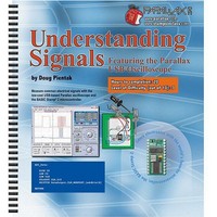
BOOK UNDERSTANDING SIGNALS
Manufacturer
Parallax Inc
Type
Signal Analysisr
Datasheet
1.70009.pdf
(137 pages)
Specifications of 70009
Style
Book
Title
Understanding Signals
Contents
Guide to Generate, View and Measure Wave Forms
Product
Microcontroller Accessories
Lead Free Status / RoHS Status
Not applicable / Not applicable
Other names
70009PAR
Available stocks
Company
Part Number
Manufacturer
Quantity
Price

Company:
Part Number:
700090B
Manufacturer:
COPAL
Quantity:
5 510
Company:
Part Number:
70009CB
Manufacturer:
VISHAY
Quantity:
5 510
Part Number:
70009GB
Manufacturer:
TI/PHILIPS
Quantity:
20 000


The trigger is set with the blue arrow to the right of the Plot Area. As you move it up and
down you will see the signal move to the right and left. This is because the trigger event
lines up in the center of the screen. A trigger event happens when the input signal crosses
the trigger voltage on a rising edge. Let’s experiment!
√
√
√
√
Adjust the trigger level up and down to see the sine wave shift left or right.
Set the Trigger Edge switch to Falling , then experiment with the trigger level.
Set the Trigger Edge switch back to Rising. C hange the
argument; try several different frequencies. Note: you will have to download the
revised program into your BASIC Stamp or HomeWork Board each time.
For each frequency tested (at least five), adjust the trigger level to capture a nice
image of the sine wave. Make a mental note regarding the volume and pitch
differences.
Signal Problems? The piezo speaker signal shown below-left resembles the one you can
reasonably expect to see when using the piezo speaker included in the Understanding
Signals kit. If you are using a different speaker, your OPTAscope display might more
closely resemble the inductive speaker signal shown below-right. Some speakers look like
piezo speakers, but they use a coil (an inductive element) instead of a piezoelectric element
to vibrate the surface that generates sound. Because the properties of a coil are very
different from the properties of a piezoelectric element, the circuit is changed drastically, and
so is the signal that is measured and displayed by the OPTAscope.
Remedy: If you do not have a true piezoelectric speaker at your disposal, you can still view
the signal by removing the speaker from the circuit shown in Figure 3-3 and Figure 3-4.
When you re-run the program and capture the signal, it should more closely resemble the
piezo speaker signal example.
Piezoelectric Speaker signal example
Inductive Speaker signal example
FREQOUT
command’s
freq1
Related parts for 70009
Image
Part Number
Description
Manufacturer
Datasheet
Request
R

Part Number:
Description:
Microcontroller Modules & Accessories Breadboard Set
Manufacturer:
Parallax Inc

Part Number:
Description:
Power Entry Modules 4AA Battery Holder
Manufacturer:
Parallax Inc

Part Number:
Description:
Microcontroller Modules & Accessories DISCONTINUED BY PARALLAX
Manufacturer:
Parallax Inc


Part Number:
Description:
COMPETITION RING FOR SUMOBOT
Manufacturer:
Parallax Inc
Datasheet:


Part Number:
Description:
TEXT INFRARED REMOTE FOR BOE-BOT
Manufacturer:
Parallax Inc
Datasheet:
Part Number:
Description:
Microcontroller Modules & Accessories DISCONTINUED BY PARALLAX
Manufacturer:
Parallax Inc
Part Number:
Description:
BOARD EXPERIMENT+LCD NX-1000
Manufacturer:
Parallax Inc
Datasheet:
Part Number:
Description:
IC MCU 2K FLASH 50MHZ SO-18
Manufacturer:
Parallax Inc
Datasheet:

Part Number:
Description:
Microcontroller Modules & Accessories AD592 Temperature Probe Sensor
Manufacturer:
Parallax Inc