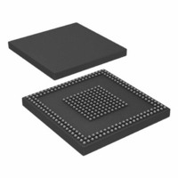
ADSP-BF527KBCZ-6C2 Analog Devices Inc, ADSP-BF527KBCZ-6C2 Datasheet - Page 5

ADSP-BF527KBCZ-6C2
Manufacturer Part Number
ADSP-BF527KBCZ-6C2
Description
IC DSP 16BIT 600MHZ 289CSPBGA
Manufacturer
Analog Devices Inc
Series
Blackfin®r
Type
Fixed Pointr
Datasheets
1.ADSP-BF531SBSTZ400.pdf
(12 pages)
2.ADSP-BF523BBCZ-5A.pdf
(88 pages)
3.ADSP-BF523KBCZ-5C2.pdf
(36 pages)
Specifications of ADSP-BF527KBCZ-6C2
Package / Case
289-CSPBGA
Interface
DMA, Ethernet, I²C, PPI, SPI, SPORT, UART, USB
Clock Rate
600MHz
Non-volatile Memory
ROM (32 kB)
On-chip Ram
132kB
Voltage - I/o
1.8V, 2.5V, 3.3V
Voltage - Core
1.10V
Operating Temperature
0°C ~ 70°C
Mounting Type
Surface Mount
Svhc
No SVHC (18-Jun-2010)
Cache On Chip L1/l2 Memory
48KB
Core Frequency Typ
600MHz
Dsp Type
Core
External Supported Memory
SDRAM, SRAM, FLASH, ROM
Interface Type
SPI, Parallel, 2 Wire
Rohs Compliant
Yes
Mmac
1200
No. Of Pins
289
Package
289CSP-BGA
Maximum Speed
600 MHz
Lead Free Status / RoHS Status
Lead free / RoHS Compliant
For Use With
ADZS-BF527-MPSKIT - BOARD EVAL MEDIA PLAYER BF527ADZS-BF527-EZLITE - BOARD EVAL ADSP-BF527
Lead Free Status / RoHS Status
Lead free / RoHS Compliant, Lead free / RoHS Compliant
Available stocks
Company
Part Number
Manufacturer
Quantity
Price
Company:
Part Number:
ADSP-BF527KBCZ-6C2
Manufacturer:
Analog Devices Inc
Quantity:
10 000
The first gain stage is composed of a low noise operational
amplifier set to an inverting configuration with integrated
50 kΩ feedback and 10 kΩ input resistors. The default micro-
phone input signal gain is 14 dB. An external resistor (R
be connected in series with the MICIN pin to reduce the first-
stage gain of the microphone input signal to as low as 0 dB by
using the following equation:
Microphone Input Gain = 50 kΩ/(10 kΩ + R
The second-stage gain of the microphone signal path is derived
from the internal microphone boost circuitry. The available set-
tings are 0 dB, 20 dB, and 40 dB and are controlled by the
MICBOOST (Register R4, Bit D0) and MICBOOST2 (Register
R4, Bit D8) bits. To achieve 20 dB of secondary gain boost, the
programmer can select either MICBOOST or MICBOOST2. To
achieve 40 dB of secondary microphone signal gain, the pro-
grammer must select both MICBOOST and MICBOOST2.
The MUTEMIC bit (Register R4, Bit D1) mutes the microphone
input signal to the ADC.
When using either the line or microphone inputs, the maximum
full-scale input to the ADC is 1.0 V rms when AVDD = 3.3 V.
Do not apply an input voltage larger than full-scale to avoid
overloading the ADC, which causes distortion of sound and
deterioration of audio quality. For best sound quality in both
microphone and line inputs, gain should be carefully configured
so that the ADC receives a signal equal to its full-scale. This
maximizes the signal-to-noise ratio for best total audio quality.
Bypass and Sidetone Paths to Output
The line and microphone inputs can be routed and mixed
directly to the output terminals by programming the SIDET-
ONE (Register R4, Bit D5) and BYPASS (Register R4, Bit D3)
registers. In both modes, the analog input signal is routed
directly to the output terminals and is not digitally converted.
The bypass signal at the output mixer is the same level as the
output of the PGA associated with each line input.
The sidetone signal at the output mixer can be attenuated from
–6 dB to –15 dB in steps of –3 dB by configuring the SIDEATT
(Register R4, Bit D6 and Bit D7) control register bits. The
ADSP-BF522C/ADSP-BF523C/ADSP-BF524C/ADSP-BF525C/ADSP-BF526C/ADSP-BF527C
MICIN
R
EXT
Figure 3. Microphone Input to ADC
AGND
AVDD
VMID
10kΩ
50kΩ
0dB/20dB/40dB
GAIN BOOST
EXT
INTERNAL CIRCUITRY
)
Rev. A | Page 5 of 36 | March 2010
EXT
ADC
OR
SIDETONE
) can
selected level of attenuation occurs after the initial microphone
signal amplification from the microphone first and second stage
gains.
Line and Headphone Outputs
The DAC outputs, the microphone (the sidetone path), and the
line inputs (the bypass path) are summed at an output mixer
(see
reo line outputs and stereo headphone outputs.
The codec has a set of efficient headphone amplifier outputs,
LHPOUT and RHPOUT, that are able to drive 16 Ω or 32 Ω
headphones (shown in
Like the line inputs, the LHPOUT and RHPOUT volumes, by
default, are independently adjusted by setting the LHPVOL
(Register R2, Bit D0 to Bit D6) and RHPVOL (Register R3, Bit
D0 to Bit D6) bits of the headphone output control registers.
The headphone outputs can be muted by writing codes less than
0110000 to the LHPVOL and RHPVOL bits.
Figure
MICROPHONE
SIDETONE/
BYPASS
OUTPUT
4). This output signal is then applied to both the ste-
DAC/
INPUT
INPUT
LINE
DAC
AGND
AVDD
VMID
AGND
AVDD
VMID
Figure 4. Output Signal Chain
Figure 5. Headphone Output
SIDETONE
BYPASS
DACSEL
Figure
5).
–
+
INTERNAL CIRCUITRY
INTERNAL CIRCUITRY
LINE OUTPUT
AND
HEADPHONE
OUTPUT
RHPOUT
or
LHPOUT


