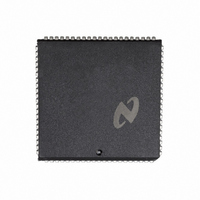
DP8344BV National Semiconductor, DP8344BV Datasheet - Page 18

DP8344BV
Manufacturer Part Number
DP8344BV
Description
IC BIPHASE COMM PROCESSR 84-PLCC
Manufacturer
National Semiconductor
Datasheet
1.DP8344BV.pdf
(184 pages)
Specifications of DP8344BV
Processor Type
8-Bit RISC
Speed
20MHz
Voltage
4.5 ~ 5.5V
Mounting Type
Surface Mount
Package / Case
84-PLCC
Operating Supply Voltage (typ)
5V
Operating Supply Voltage (max)
5.5V
Operating Supply Voltage (min)
4.5V
Mounting
Surface Mount
Operating Temperature (max)
70C
Operating Temperature (min)
0C
Operating Temperature Classification
Commercial
Lead Free Status / RoHS Status
Contains lead / RoHS non-compliant
Features
-
Lead Free Status / Rohs Status
Not Compliant
Other names
*DP8344BV
Available stocks
Company
Part Number
Manufacturer
Quantity
Price
Company:
Part Number:
DP8344BV
Manufacturer:
NSC
Quantity:
5 510
Part Number:
DP8344BV
Manufacturer:
NS/国半
Quantity:
20 000
2-3 show a write to ACR that loads starts selects the
2 0 CPU Description
2 1 2 1 Timer Operation
After the desired 16-bit time-out value is written into TRL
and
achieved in a single write to ACR
changing the timer clock frequency in that TCS should not
be changed while the timer is running (i e
After a write to ACR to load and start the timer the timer
begins counting down at the selected frequency from the
value in TRL and TRH
the timer interrupt is generated and the timer reloads the
current word from TRL and TRH to cycle through a
countdown again The timing waveforms shown in Figure
CPU clock rate 2 for the countdown rate and asserts the
Global Interrupt Enable GIE Prior to the write to ACR
tively the timer interrupt was unmasked in the Interrupt
Control Register ICR by clearing bit 4 and zero instruc-
tion wait states were selected in DCR
the CPU will vector to the timer interrupt service routine
address when the timer reaches a count of zero The timer
interrupt is the lowest priority interrupt and is latched and
maintained until it is cleared in software (See CPU Inter-
rupts section) For very long time intervals time-outs can be
accumulated under software control by writing a one to TO
in CCR allowing the timer to recycle its count down with
no other intervention For time-outs attainable with one
count down stopping the timer will clear the interrupt and
interrupt service routine occurs at different instruction
boundaries depending on when the timer interrupt occurs in
the instruction cycle If the timer times out prior to T2 where
T2 is the last T-state of an instruction cycle the call to the
interrupt service routine will occur in the next instruction
When the time-out occurs in T2 the call to the interrupt
service routine will not occur in the next instruction It occurs
in the second instruction following T2
TO
TRL and TRH were loaded with 00h and 01h respec-
ACR asserted GIE
TRH
When the timer interrupt is enabled the call to the
the start load and clock selection can be
the timer interrupt is enabled and
Upon reaching a count of zero
(Continued)
A restriction exists on
Since the write to
TST is high)
18
The count status of the timer can be monitored by reading
put of the timer not the value in the input holding registers
is presented to the ALU Some applications might require
monitoring the count status of the timer while it is counting
down Since the timer can time-out between reads of TRL
and TRH the software should take this fact into consider-
ation To read back what was written to TRL and TRH
the timer must first be loaded via TLD without starting the
timer followed by a one instruction delay before reading
ed from the load operation
To determine the time-out delay for a given value in TRL
and TRH other than 0000h the following equation can be
used
where
struction that asserts TST in ACR
When the value of 0000h is loaded in the timer the maxi-
mum time-out is obtained and is calculated as follows
With the CPU running full speed with an 18 8 MHz crystal
the maximum single loop time delay attainable would be
55 6 ms ( TCS
same constraints is 106 ns ( TCS
time-out intervals the total time delay is simply the number
of loops accumulated multiplied by the calculated time de-
lay The equations above do not account for any overhead
for processing the timer interrupt The added overhead of
processing the interrupt may need to be included for preci-
sion timing
TRL and or TRH
TRL and TRH to allow the output registers to be updat-
k
T
TD
e
e
e
2 when TCS
The period of the CPU clock
The amount of time delay after the end of the in-
TD
e
e
(value in TRH TRL ) T k
TD
0) The minimum time delay with the
e
When the registers are read the out-
e
1 or 16 when TCS
65536 T k
e
1) For accumulating
e
0


