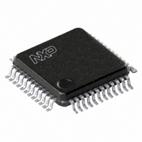
TDA8007BHL/C3,118 NXP Semiconductors, TDA8007BHL/C3,118 Datasheet - Page 23

TDA8007BHL/C3,118
Manufacturer Part Number
TDA8007BHL/C3,118
Description
IC INTERFACE CARD MP 48-LQFP
Manufacturer
NXP Semiconductors
Datasheet
1.TDA8007BHLC3118.pdf
(51 pages)
Specifications of TDA8007BHL/C3,118
Controller Type
Multiprotocol IC Card Interface
Interface
Parallel
Voltage - Supply
2.7 V ~ 6 V
Current - Supply
315mA
Operating Temperature
-40°C ~ 85°C
Mounting Type
Surface Mount
Package / Case
48-LQFP
Maximum Operating Temperature
+ 85 C
Minimum Operating Temperature
- 40 C
Mounting Style
SMD/SMT
Lead Free Status / RoHS Status
Lead free / RoHS Compliant
Other names
568-3520-2
935272525118
TDA8007BHLBE-T
935272525118
TDA8007BHLBE-T
Available stocks
Company
Part Number
Manufacturer
Quantity
Price
Company:
Part Number:
TDA8007BHL/C3,118
Manufacturer:
NXP Semiconductors
Quantity:
10 000
NXP Semiconductors
TDA8007BHL
Product data sheet
If LCT mode is used for transmitting the last character, then bit TBE is not set at the end of
the transmission.
Table 19.
[1]
Table 20.
Bit
7
6
5
4
3
2
1
0
TO3
Register value at reset: all relevant bits are cleared after reset.
7
Symbol
TO3
TO2
TO1
EA
PE
OVR
FER
TBE/RBF
Register USR (address 0Eh; read only)
Description of USR bits
TO2
All information provided in this document is subject to legal disclaimers.
6
Rev. 8 — 11 January 2011
Description
Time-Out counter 3. Bit TO3 is set when counter 3 has reached its
terminal count.
Time-Out counter 2. Bit TO2 is set when counter 2 has reached its
terminal count.
Time-Out counter 1. Bit TO1 is set when counter 1 has reached its
terminal count.
Early answer is high if the first START bit on the I/O during ATR has
been detected between the first 200 and 368 clock pulses with RST low
(all activities on the I/O during the first 200 clock pulses with RST low
are not taken into account) and before the first 368 clock pulses with
RST high. These two features are re-initialized at each toggling of RST
Parity Error (PE). In protocol T = 0, bit PE = 1 if the UART has
detected a number of received characters with parity errors equal to the
number written in bits PEC2, PEC1 and PEC0 or if a transmitted
character has been NAK by the card a number of times equal to the
value programmed in bits PEC2, PEC1 and PEC0. It is set at 10.5 ETU
in the reception mode and at 11.5 ETU in the transmission mode.
In protocol T = 0, a character received with a parity error is not stored in
register FIFO (the card should repeat this character). In protocol T = 1,
a character with a parity error is stored in the FIFO and the parity error
counter is not active.
Overrun (OVR). Bit OVR = 1 if the UART has received a new character
whilst register FIFO was full. In this case, at least one character has
been lost.
Framing Error (FER). Bit FER = 1 when pin I/O was not in the high
impedance state at 10.25 ETU after a START bit. It is reset when
register USR has been read-out.
Transmission Buffer Empty (TBE)/Reception Buffer Full (RBF).
Bits TBE and RBF share the same bit within register USR: when in
transmission mode the relevant bit is TBE; when in reception mode it is
RBF.
Bit TBE = 1 when the UART is in transmission mode and when the
microcontroller may write the next character to transmit in register UTR.
It is reset when the microcontroller has written data in the transmit
register or when bit T/R within register UCR1 has been reset either
automatically or by software. After detection of a parity error in
transmission, it is necessary to wait 13.5 ETU before rewriting the
character which has been NAK by the card. (Manual mode, see
Table 18)
Bit RBF = 1 when register FIFO is full. The microcontroller may read
some of the characters in register URR, which clears bit RBF.
TO1
5
EA
4
[1]
PE
3
Multiprotocol IC card interface
OVR
2
TDA8007BHL
FER
© NXP B.V. 2011. All rights reserved.
1
TBE/RBF
23 of 51
0


